

Differential mechanism assembly
a technology of differential mechanism and assembly, which is applied in the direction of differential gearings, belts/chains/gearrings, differential gearings, etc., can solve the problems of manual operation that requires considerable dexterity, and achieve the effects of reducing the thickness of the differential case wall, reducing the elongation of the differential pinion shaft hole, and increasing stiffness
- Summary
- Abstract
- Description
- Claims
- Application Information
AI Technical Summary
Benefits of technology
Problems solved by technology
Method used
Image

Examples
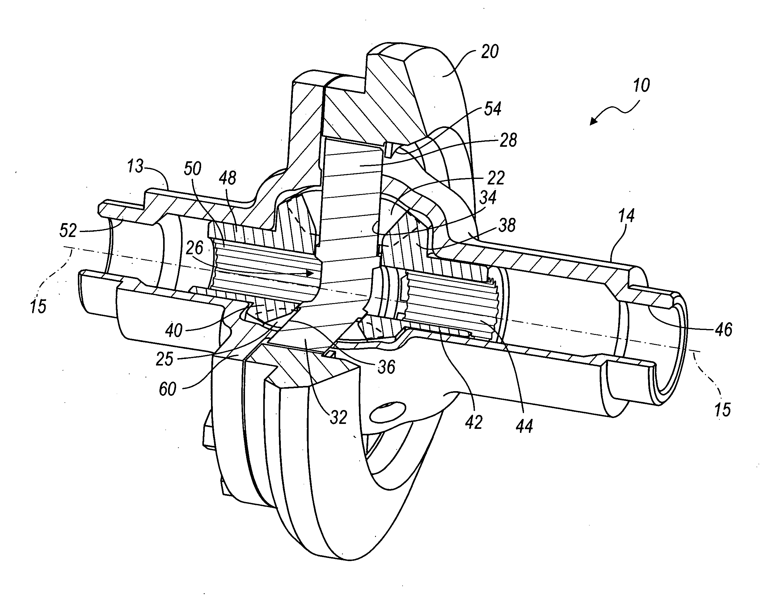
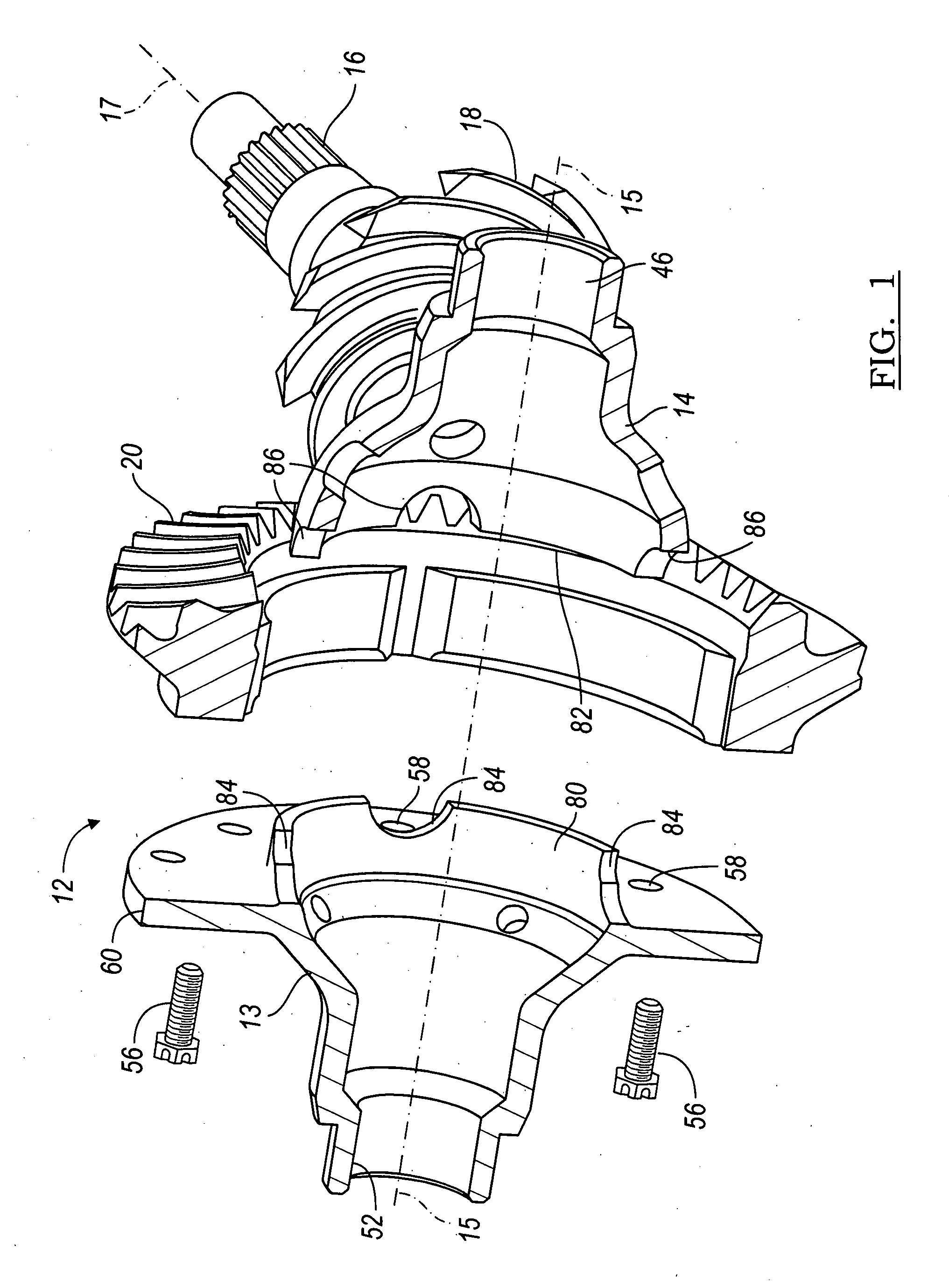
case portion 13
[0041]Case portion 13 includes an axial protrusion 80, which contacts an annular rim 82 on case portion 14, when the parts are assembled. The axial protrusion 80 is formed with a series of arcuate recesses 84, spaced angularly about axis 15. Each recess 84 partially surrounds a respective spider pin 28, 30, 32 (as shown in FIG. 6) and is aligned with a spider pin hole portion 86 formed in case portion 14. Each recess 84 and hole portion 86 complete a circular or slotted hole 88, which contains a spider pin 28, 30, 32 when the case is assembled.
[0042]FIGS. 3 and 4 illustrate an alternative embodiment of a differential assembly 62, in which two differential case portions 64, 66 are secured mutually and to a ring gear 67 by a series of bolts, each bolt being fitted into a hole 68 located on a circle of bolt holes formed in a radial flange 70 on case portion 64 and a hole 72 located on a circle of bolt holes formed in a radial flange 74 and aligned with a hole 68 on case portion 66. Fla...
case portion 64
[0044]Case portion 64 includes an annular, axial-extending protrusion 80, which contacts an annular rim 82 on case portion 66, when the parts are assembled, as shown in FIG. 4. The axial protrusion 80 is formed with a series of arcuate recesses 84, spaced angularly about axis 15. Each recess 84 partially surrounds its respective spider pin 28, 30, 32 and is aligned with a spider pin hole portion 86 formed in case portion 66. Each recess 84 and hole portion 86 complete a circular hole 88, which contains a spider pin 28, 30, 32 when the case is assembled as shown in FIG. 4.
[0045]FIG. 5 illustrates the pinions 22-25 supported on a case portion 14, 66 for rotation about the spider pins 28, 30, 32. FIG. 6 shows parallel slots 90 formed at diametrically opposite sides of spider pin 30, and parallel slots 92 formed at diametrically opposite sides of spider pin 32. A clip 94 includes legs 96, 97, each of which engages a slot 90 on spider pin 30, and legs 98, 99, each of which is similar res...
first embodiment
[0049]FIG. 10A shows the first embodiment, the open differential 10 of FIGS. 1-4, whose case portion 13 includes the annular, axial-extending protrusion 80.
PUM
 Abstract
Description
Claims
Application Information