
Router for smart home

A smart home and router technology, applied in the direction of selecting devices, electrical components, etc., can solve the problems of reducing the service life of the plug interface, residual network cables, and no installation method, achieving a stable clamping effect, easy disassembly and maintenance, and convenient installation. effect of the way

Inactive Publication Date: 2021-02-23
安徽竣阳信息技术有限公司
View PDF0 Cites 2 Cited by
  • Summary
  • Abstract
  • Description
  • Claims
  • Application Information

AI Technical Summary

Problems solved by technology

[0004] The purpose of the present invention is to provide a router for smart home use, which mainly solves certain defects of existing routers for smart home use. Generally, it is difficult to assemble routers, requiring a large number of screws, and the time required for assembly is relatively long. , does not have a convenient installation method, and is not convenient for quick disassembly and maintenance of the router, and the redundant part of the network cable connected to the router often remains outside, resulting in multiple network cables being entangled or dragged, and cannot be adjusted according to actual needs The length of the network cable outside the router does not have the function of tidying up the tangled wires very well, and most of the plug-in ports of the router are usually exposed to the outside world, making it easy for dust or water in the outside air to enter the plug-in port, thereby causing Poor contact or even aging at the interface reduces the service life of the plug interface and does not play a good protective role

Method used


Image

  • Router for smart home
  • Router for smart home
  • Router for smart home

Examples


Embodiment Construction

[0032] The technical solutions in the embodiments of the present invention will be clearly and completely described below in conjunction with the embodiments of the present invention. Apparently, the described embodiments are only some of the embodiments of the present invention, not all of them. Based on the embodiments of the present invention, all other embodiments obtained by persons of ordinary skill in the art without creative efforts fall within the protection scope of the present invention.

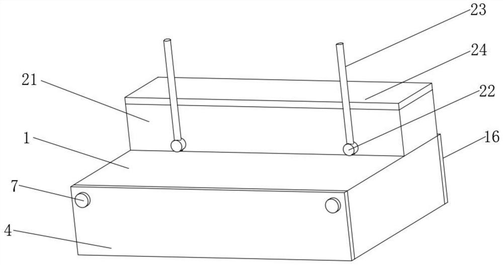
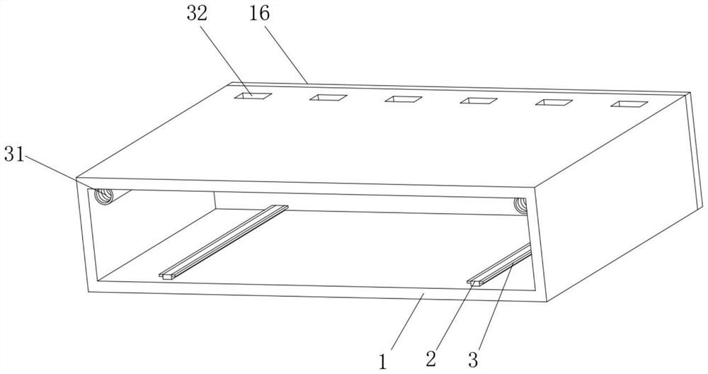
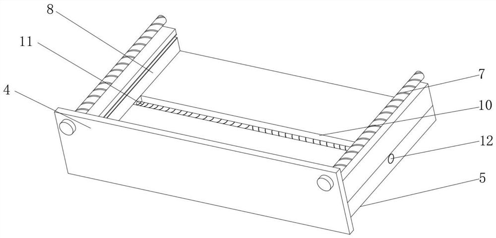
[0033] like Figure 1-7 As shown, a smart home router includes a main body shell 1, and fixed rods 2 are fixedly installed on both sides of the inner bottom of the main body shell 1. One side of the installation cover 4 is provided with an installation cover 4, and the inner surface of the installation cover 4 is fixedly installed with a plug-in horizontal plate 5 near the bottom. Long bolt rods 7 are installed on one side near the two corners, long threaded pipes 31 are fixedly ...


PUM


Abstract

Disclosed is a router for a smart home. The router comprises a main body shell, fixing rods are fixedly installed on the portions, close to the two sides, of the bottom surface of the interior of themain body shell, limiting clamping rods are fixedly connected to the two sides of the two fixing rods, and a mounting cover plate is arranged on one side of the main body shell; an inserting transverse plate is fixedly mounted on the inner side face, close to the bottom, of the mounting cover plate, limiting clamping grooves are formed in the positions, close to the two sides, of the lower surfaceof the inserting transverse plate in a penetrating mode, and long bolt rods are arranged on one side face, close to the two corners, of the mounting cover plate in a penetrating mode. The router provided by the invention is short in assembly time, has a convenient installation mode, is also convenient to disassemble and overhaul quickly, avoids network cable winding or dragging caused by residualredundant network cables outside, has a very good cable arranging and winding function, and prevents dust or water in external air from entering a plugging port to cause poor contact and even aging,so that the service life of the plugging port is prolonged, and a very good protection effect is achieved.

Description

technical field [0001] The invention belongs to the field of smart home, in particular to a router for smart home. Background technique [0002] A router is a device that connects various local area networks and wide area networks in the Internet. It automatically selects and sets routes according to channel conditions, and sends signals in the best path and in sequence. A router is used to connect multiple logically separated networks. The so-called logical network represents a separate network or a subnet. When data is transferred from one subnet to another, it is done through a router. At present, routers have been widely used in all walks of life, and various products of different grades have become the main force to realize the internal connection of various backbone networks, the interconnection between backbone networks, and the interconnection between backbone networks and the Internet; [0003] The existing smart home routers still have certain defects. Generally,...

Claims


Application Information

Patent Timeline
Patent Type & Authority Applications(China)
IPC IPC(8): H04Q1/02H04Q1/04
CPCH04Q1/02H04Q1/028H04Q1/04H04Q1/114
Inventor 李松
Owner 安徽竣阳信息技术有限公司
Learn More