High-temperature constant-power electric tracing band
An electric heating cable and constant power technology, which is applied in the direction of electric heating devices, ohmic resistance heating, electrical components, etc., can solve the problems of pulling the heating cable, pulling the heating cable, affecting the stability of the heating cable, etc.
- Summary
- Abstract
- Description
- Claims
- Application Information
AI Technical Summary
Problems solved by technology
Method used
Image

Examples
Embodiment 1
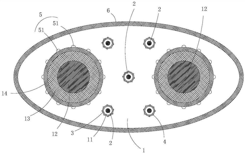
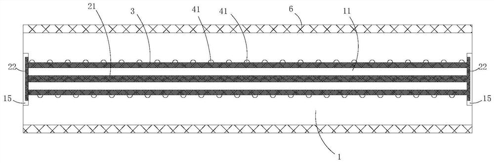
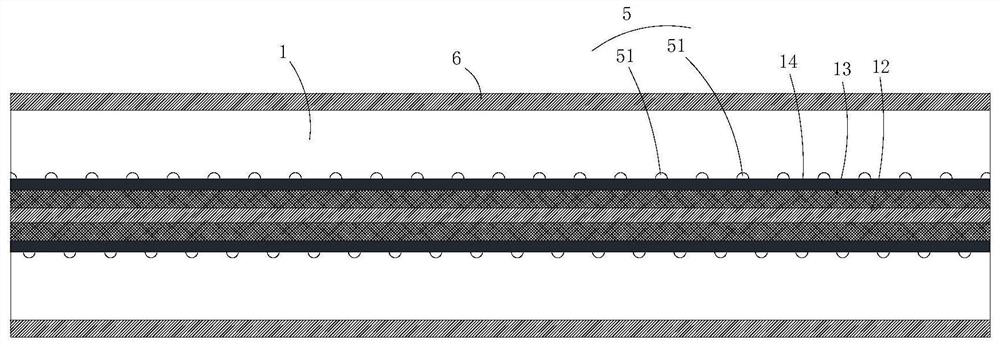
[0037] Such as Figure 1 to Figure 3 As shown, the present invention provides a high-temperature constant power electric heating cable, including: an insulating filling tape 1, and a perforation 11 and a wire 12 are arranged at intervals in the insulating filling tape 1, and the outer surface of the wire 12 and the insulation A composite layer 13 is arranged between the filling strips 1, and a heat conduction layer 14 is arranged between the outer surface of the composite layer 13 and the insulating filling strip 1. In the length direction of the insulating filling strip 1, the perforation 11 It has a first port and the second port; an elastic contraction part 2, one end of the elastic contraction part 2 is connected to the first port of the perforation 11, and the other end of the elastic contraction part 2 is connected to the At the second port of the through hole 11, the elastic contraction member 2 is in a contracted state in the through hole 11.
[0038] It can be unders...
Embodiment 2
[0044] The difference between this embodiment and the foregoing embodiment is:
[0045] In some embodiments of the present invention, the inner wall of the perforation 11 is provided with a heat insulating layer 3 surrounding the elastic contraction member 2 . Thus, the heat generated by the wire 12 is prevented from damaging the elastic contraction member 2 .
[0046]In some embodiments of the present invention, in the length direction of the insulating filling tape 1, a plurality of first positioning portions 4 are arranged at intervals on the outer wall surface of the heat insulating layer 3, and each of the first positioning portions 4 all protrude into the insulating filling strip 1 to limit the displacement between the insulating filling strip 1 and the heat insulating layer 3 . Thus, the stability of the heating cable is improved.
[0047] In some embodiments of the present invention, each of the first positioning portions 4 includes a plurality of first positioning p...
Embodiment 3
[0051] The difference between this embodiment and the foregoing embodiment is:
[0052] In some embodiments of the present invention, there are a plurality of elastic contraction members 2, and a plurality of perforations 11 are provided at intervals in the insulating filling tape 1, and a plurality of elastic contraction members 2 are arranged in one-to-one correspondence. Inside a plurality of said perforations 11. Thus, the elastic force of the elastic contraction member 2 is improved to better protect the electric heating cable.
[0053] In some embodiments of the present invention, in the length direction of the insulating filling tape 1, a plurality of second positioning parts 5 are arranged at intervals on the outer wall surface of the heat conducting layer 14, each of the second positioning parts 5 Both protrude into the insulating filling strip 1 to limit the displacement between the insulating filling strip 1 and the heat conducting layer 14 . Thus, the stability o...
PUM
 Abstract
Description
Claims
Application Information
 - R&D
- Intellectual Property
- Life Sciences
- Materials
- Tech Scout
- Unparalleled Data Quality
- Higher Quality Content
- 60% Fewer Hallucinations
Browse by: Latest US Patents, China's latest patents, Technical Efficacy Thesaurus, Application Domain, Technology Topic, Popular Technical Reports.
© 2025 PatSnap. All rights reserved.Legal|Privacy policy|Modern Slavery Act Transparency Statement|Sitemap|About US| Contact US: help@patsnap.com