
Steel pipe paint brushing device for buildings

A technology for steel pipe brushing and construction, applied in the direction of spraying devices, etc., can solve the problems of pollution, uneven painting, time-consuming and laborious, and achieve the effect of avoiding environmental pollution.

Inactive Publication Date: 2021-02-26
孙冬叶
View PDF6 Cites 0 Cited by
  • Summary
  • Abstract
  • Description
  • Claims
  • Application Information

AI Technical Summary

Problems solved by technology

Most of the existing steel pipes are painted manually, which is not only time-consuming and laborious, but also causes uneven paint coating, resulting in uneven paint coating thickness and increased corrosion rate of steel pipes, and the paint will splash around during the painting process, resulting in Pollution

Method used


Image

  • Steel pipe paint brushing device for buildings
  • Steel pipe paint brushing device for buildings
  • Steel pipe paint brushing device for buildings

Examples


Embodiment 1

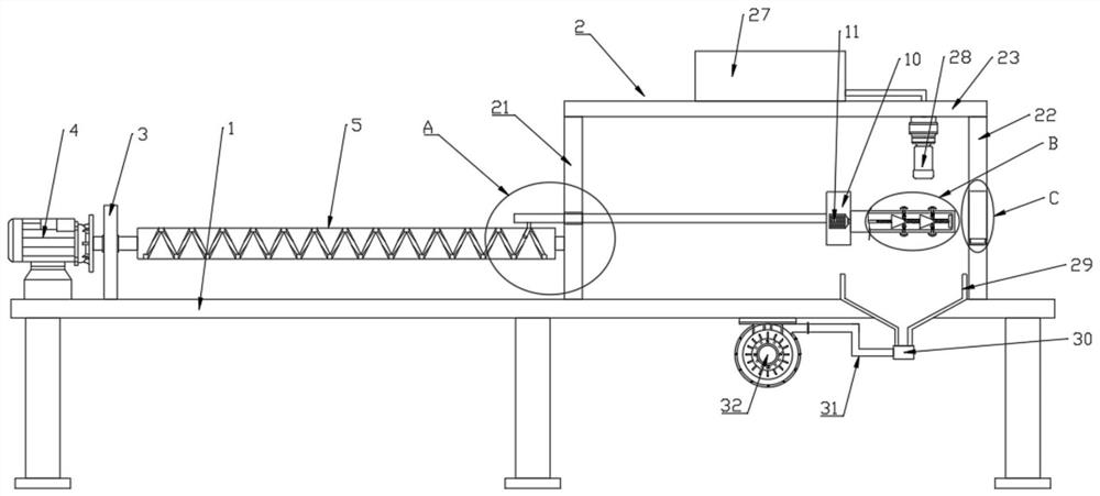
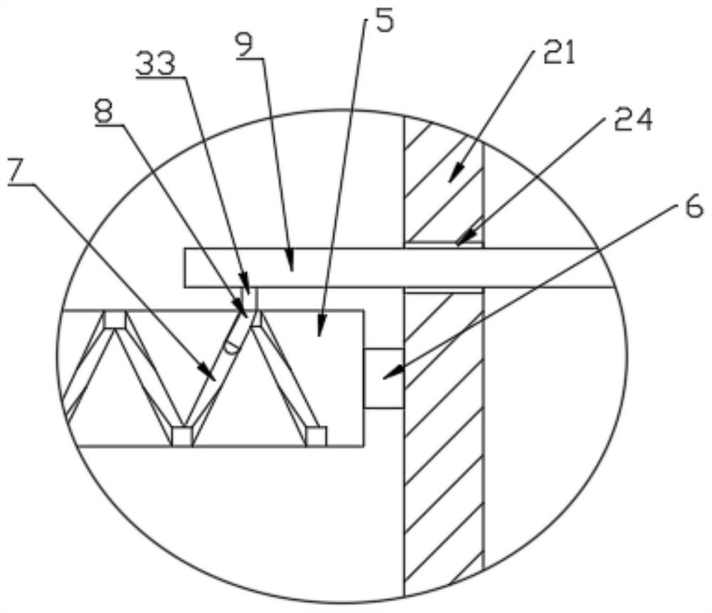
[0024] see Figure 1-5 , a steel pipe painting device for construction, including a workbench 1, a placing frame 2, a painting assembly 27, a clamping mechanism, and a driving mechanism for driving the clamping mechanism to reciprocate and rotate, and the placing frame 2 includes a left support plate 21. The right support plate 22 and the top plate 23 fixed on the top of the left support plate 21 and the right support plate 22, the left support plate 21 is provided with a rotation groove 24, and the right support plate 22 is provided with a placement groove 25. A plurality of rotating wheels 26 are arranged for rotation in the placement groove 25, and the clamping mechanism is located in the placement frame 2, and the driving mechanism includes a support base 3, a servo motor 4 and a transmission screw 5, and the support base 3 is fixedly located on the The top surface of the workbench 1, and the rotating shaft 6 is arranged between the support seat 3 and the placement frame 2...

Embodiment 2

[0027] This embodiment expands the functions on the basis of Embodiment 1, specifically:

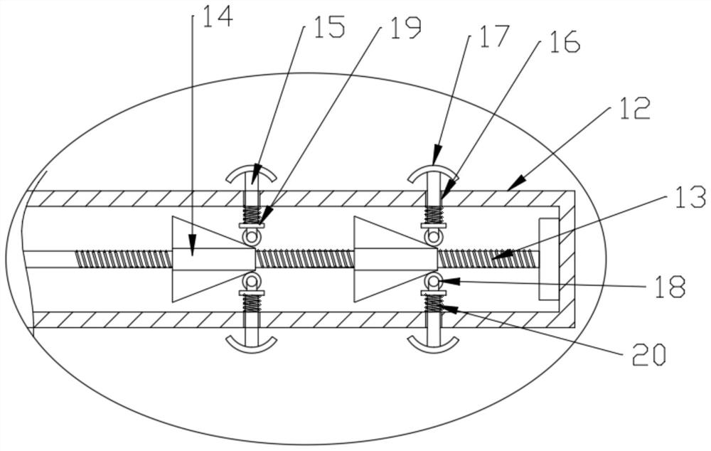
[0028] The clamping mechanism includes a driving motor 11, a supporting horizontal tube 12, a rotating screw 13, a moving block 14 and a push rod 15. The supporting horizontal tube 12 is fixedly connected with the turntable 10, and the axis of the supporting horizontal tube 12 is connected with the transmission The axis centers of the lead screw 5 are parallel, the rotating lead screw 13 is installed in the support horizontal tube 12, and the rotating lead screw 13 is driven by the drive motor 11 provided in the turntable 10, and the rotating lead screw 13 is located in the support horizontal tube The rod body of 12 is provided with a moving block 14 threaded with it, and a plurality of through holes 16 are provided on the support horizontal tube 12, and the push rod 15 is slidably connected with the through holes 16, and the push rod 15 is positioned on the support horizontal tube 12. T...


PUM


Abstract

The invention discloses a steel pipe paint brushing device for buildings. The device comprises a workbench, a placing frame, a paint spraying assembly, a clamping mechanism and a driving mechanism used for driving the clamping mechanism to reciprocate and rotate, the clamping mechanism is located in the placing frame, and the driving mechanism is arranged, so that a steel pipe rotates and horizontally reciprocates in the placing frame at the same time; the paint spraying assembly on the placing frame is matched, so that all-directional paint spraying on a steel pipe is realized; and by arranging the clamping mechanism, compared with an existing steel pipe clamping mechanism, the clamping mechanism fixes the steel pipe from the interior of the steel pipe, and the phenomenon that in the steel pipe clamping process of an existing steel pipe clamping device, the outer wall of the steel pipe is in rigid contact, and consequently the surface of the steel pipe is damaged is avoided.

Description

technical field [0001] The invention relates to the technical field of construction, in particular to a steel pipe painting device for construction. Background technique [0002] Steel pipes are used to transport fluids and powdery solids, exchange heat, and manufacture mechanical parts and containers. There are two kinds of seam steel pipe and spiral seam welded pipe. In construction engineering, steel pipe is an important raw material, and when some steel pipes are used, due to the different use environments, it is necessary to paint the surface of the steel pipe to prevent the steel pipe from rusting and corrosion, or to play an aesthetic role. Most of the existing steel pipes are painted manually, which is not only time-consuming and laborious, but also causes uneven paint coating, resulting in uneven paint coating thickness and increased corrosion rate of steel pipes, and the paint will splash around during the painting process, resulting in pollute. Contents of the...

Claims


Application Information

Patent Timeline
Patent Type & Authority Applications(China)
IPC IPC(8): B05B13/02B05B14/00
CPCB05B13/0207B05B13/0235B05B14/00
Inventor 孙冬叶
Owner 孙冬叶
Learn More