Sewage disposal device

A technology for cleaning and supporting pipes, applied in cleaning methods and appliances, cleaning methods using liquids, chemical instruments and methods, etc., can solve problems such as dust contamination of power supply equipment, tripping of equipment pollution flashover lines, dust pollution of power supply facilities, etc. Achieve the effect of meeting the needs of cleaning or fire extinguishing, solving circuit failures or accidents, and quick and easy installation

Inactive Publication Date: 2021-02-26
MEIZHOU POWER SUPPLY BUREAU OF GUANGDONG POWER GRID CORP
View PDF6 Cites 1 Cited by
  • Summary
  • Abstract
  • Description
  • Claims
  • Application Information

AI Technical Summary

Problems solved by technology

Among them, due to the serious dust and fog in some mountainous areas, and the power supply facilities are often polluted by construction along the way or road dust, for example, it will cause power supply equipment such as insulators, switches, isolation, transformers to be contaminated with dust, which will lead to equipment pollution flashover and line tripping

Method used


Image

  • Sewage disposal device
  • Sewage disposal device
  • Sewage disposal device

Examples


Embodiment 1

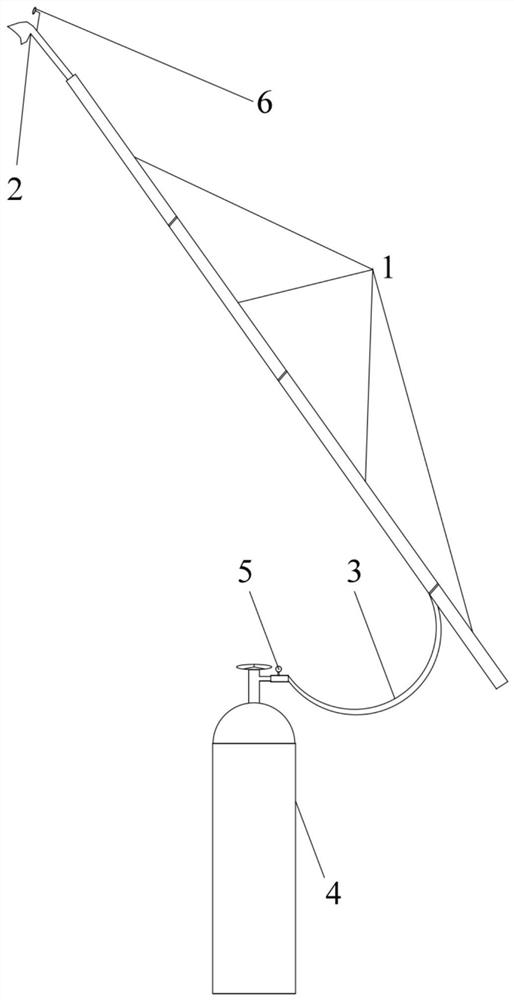
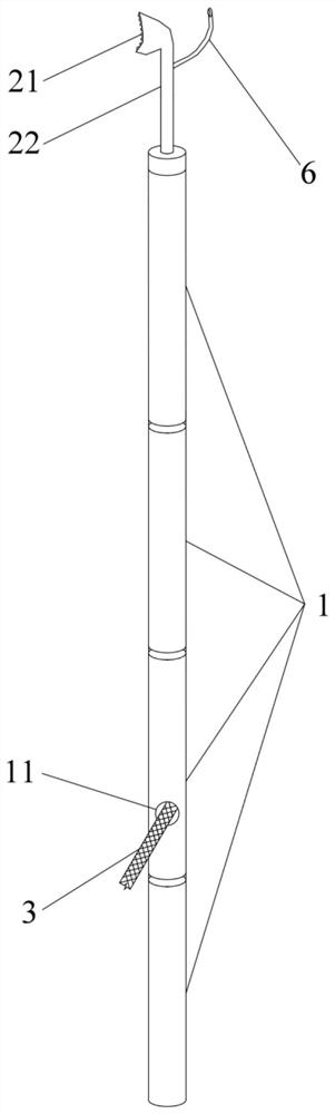
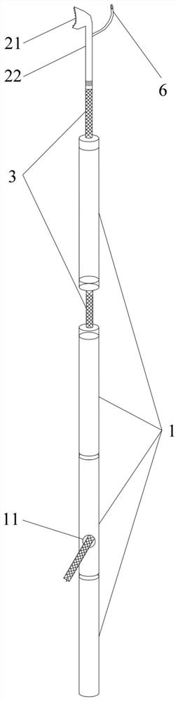
[0040] see Figure 1 to Figure 5 , the present embodiment provides a cleaning device, including a support rod, a nozzle 2, a pressure pipe 3 and a pressure gas cylinder 4, wherein the support rod is formed by sequentially connecting a plurality of support pipes 1 in the axial direction, and one end of the support rod serves as an operating One end is used to set the nozzle 2, the other end is used as the working end for the operator to hold, the nozzle 2 is detachably connected to the support tube 1 at the working end of the support rod, the pressure pipe 3 is in the support rod, and one end is connected to the nozzle 2 , the other end passes through the support rod and is connected to the pressure gas cylinder 4.

[0041] In the above arrangement, a plurality of support tubes 1 are combined to form a firm support rod structure. The nozzle 2 is installed and disassembled on the support tube 1 at the working end of the support rod. A pressure pipe 3 is pierced inside the suppor...

Embodiment 2

[0057] The second embodiment discloses a cleaning device whose structure is basically the same as that of the first embodiment. The cleaning device includes a support rod, a nozzle 2, a pressure pipe 3, a pressure gas cylinder 4, a pressure valve 5 and a camera 6, and the support rod is composed of a plurality of support pipes 1 to form a firm support structure. The support pipe 1 at the working end of the support rod The spray head 2 is installed and disassembled on the top, and the support rod composed of a plurality of support pipes 1 is pierced with a pressure pipe 3, one end of the pressure pipe 3 is connected to the spray head 2, and the other end is connected to the pressure cylinder 4 through the pressure valve 5, and the camera 6 It is detachably installed on the nozzle 2. The configuration of the above structures, the specific structures further included and their connection methods are the same as those in the first embodiment.

[0058] see Figure 1 to Figure 3 ,...


PUM


Abstract

The invention relates to the field of sewage disposal equipment, in particular to a sewage disposal device. The sewage disposal device comprises a supporting rod, a spray head, a pressure pipeline anda pressure gas cylinder, wherein the supporting rod is formed by sequentially connecting a plurality of supporting pipes in the axial direction, one end of the supporting rod is an operation end, andthe other end of the supporting rod is a working end; the spray head is detachably connected to the supporting pipe at the working end of the supporting rod; and the pressure pipeline is arranged inthe supporting rod composed of the supporting pipes in a penetrating mode, one end of the pressure pipeline communicates with the spray head, and the other end of the pressure pipeline penetrates outof the supporting rod to be connected to the pressure gas cylinder. The sewage disposal device is rapid, simple and convenient to install, so that the sewage disposal device can rapidly and effectively carry out sewage disposal on electric equipment, and circuit fault opening is prevented; meanwhile, different gases are loaded in the detachable spray head and the pressure gas cylinder to realize the sewage disposal or fire extinguishing function, so that the sewage disposal or fire extinguishing requirements are met; and the sewage disposal device is simple to operate, high in efficiency, suitable for various circuit places and capable of effectively solving the problem of circuit faults or accidents with different natures.

Description

technical field [0001] The invention relates to the field of cleaning equipment, in particular to a cleaning device. Background technique [0002] With the rapid development of electric power technology and users' demand for electric energy, the requirements for the reliability of power supply and the quality of electric energy are getting higher and higher in the process of electric power operation. Among them, due to the serious dust and fog in some mountainous areas, and the power supply facilities are often polluted by construction along the way or road dust, for example, it will cause power supply equipment such as insulators, switches, isolation, and transformers to be contaminated with dust, which will cause equipment pollution flashover and line tripping. [0003] Some lines with reclosing function in the power supply system can reclose successfully, but some lines without reclosing function cannot. It is necessary to use technical means to avoid such transient or pe...

Claims


Application Information

Patent Timeline
Patent Type & Authority Applications(China)
IPC IPC(8): B08B3/02B08B13/00A62C13/64A62C13/76A62C31/02
CPCB08B3/02B08B13/00A62C13/64A62C13/76A62C31/02
Inventor 徐宣蔡延明刘锦旭陈亦壮欧阳钢铁张仕昌黄力谭书铭刘路路
Owner MEIZHOU POWER SUPPLY BUREAU OF GUANGDONG POWER GRID CORP
Why Eureka
Try Eureka