Crystal ingot stripping method and crystal ingot stripping device

A crystal ingot and accommodating cavity technology, applied in laser welding equipment, electrical components, circuits, etc., can solve the problems of scattered processing procedures and inability to handle materials

Active Publication Date: 2021-02-26
SONGSHAN LAKE MATERIALS LAB +1
View PDF6 Cites 4 Cited by
  • Summary
  • Abstract
  • Description
  • Claims
  • Application Information

AI Technical Summary

Problems solved by technology

Although the above method can effectively process the surface of the material, it cannot process

Method used


Image

  • Crystal ingot stripping method and crystal ingot stripping device
  • Crystal ingot stripping method and crystal ingot stripping device
  • Crystal ingot stripping method and crystal ingot stripping device

Examples


Embodiment 1

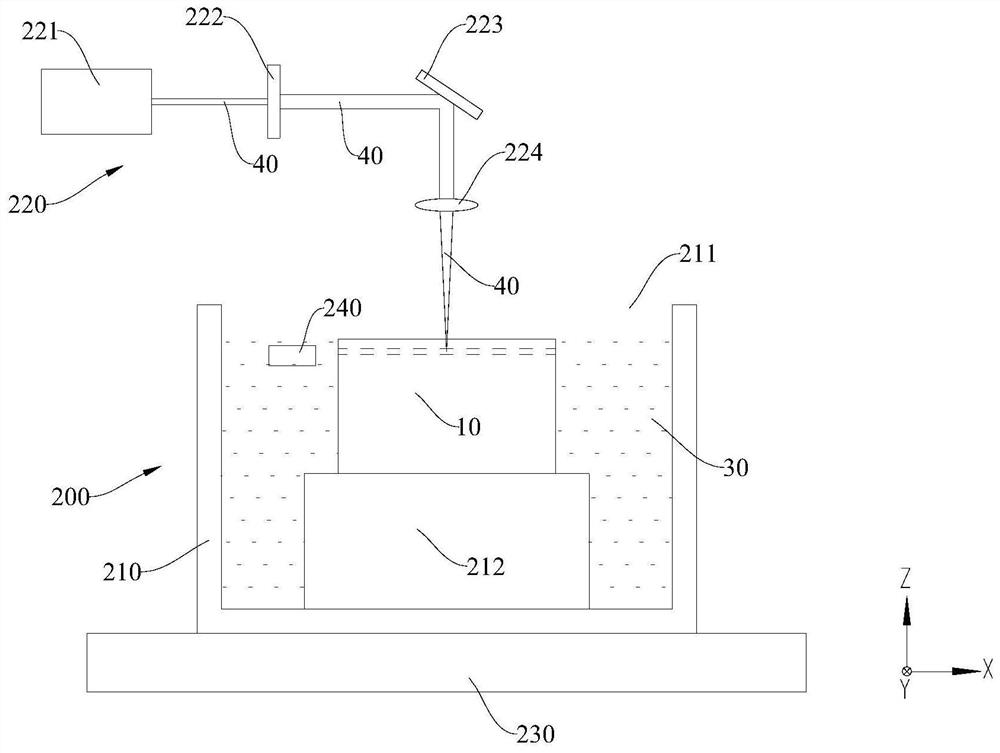
[0063] A kind of crystal ingot stripping device 200, such as image 3 As shown, it includes: a housing body 210 , a laser component 220 , a motion platform 230 and a magnetic component 240 . in:

[0064] The accommodating body 210 has an accommodating cavity 211 for accommodating the magnetorheological fluid 30 and the crystal ingot 10 , and the bottom of the accommodating cavity 211 is provided with a support platform 212 for fixing the crystal ingot 10 on the upper surface.

[0065] The laser assembly 220 is disposed above the housing body 210 , and includes a laser 221 , a beam expander 222 , a reflector 223 and a focusing mirror 224 . The laser 221 , the beam expander 222 and the reflector 223 are arranged at intervals along the horizontal direction;

[0066] The motion platform 230 is disposed at the bottom of the accommodating body 210 and is configured to be able to move along the X direction, the Y direction and the Z direction.

[0067] The magnet assembly 240 incl...

Embodiment 2

[0069] A method for stripping an ingot, carried out using the ingot stripping device 200 provided in Embodiment 1, comprising:

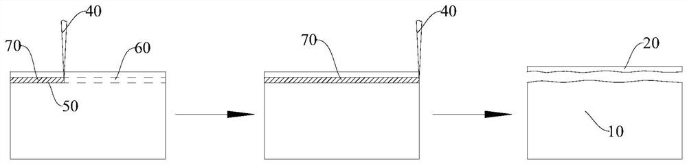
[0070] The silicon carbide ingot 10 to be stripped is placed on the upper surface of the supporting platform 212 , and the magnetorheological fluid 30 is filled in the accommodating cavity 211 .

[0071]According to the thickness of 350 μm of the silicon carbide wafer 20 to be peeled off, the relative height of the ingot 10 is adjusted by moving the motion platform 230 in the Z direction, so as to focus the laser beam 40 at a preset depth of 450 μm inside the silicon carbide ingot 10 . Wherein, the pulse width of the laser beam 40 is 4ns, the wavelength is 1064nm, and the power is 3W.

[0072] The laser beam 40 is scanned inside the ingot 10 so that a modified layer is formed inside the silicon carbide ingot 10 . Wherein, the scanning speed is 300mm / s. The scanning path is: control the motion platform 230 to move in the X direction, so that the la...

Embodiment 3

[0076] A kind of ingot stripping method, adopts the crystal ingot stripping device 200 that embodiment 1 provides to carry out, and its difference with embodiment 2 is:

[0077] The crystal ingot 10 to be peeled off is a silicon crystal ingot 10 .

[0078] The pulse width of the laser beam 40 is 10 ps, ​​the wavelength is 1030 nm, and the power is 2 W; the scanning speed is 400 mm / s.


PUM

PropertyMeasurementUnit
Pulse widthaaaaaaaaaa
Thicknessaaaaaaaaaa

Abstract

The embodiment of the invention provides a crystal ingot stripping method and a crystal ingot stripping device, and belongs to the technical field of semiconductor substrate preparation. The crystal ingot stripping method comprises the steps that a laser beam is focused at a preset depth in a crystal ingot in magnetorheological fluid, and scanning processing of a preset stripping surface at the preset depth of the crystal ingot is completed through the laser beam so that a modified layer can be formed on the preset stripping surface; and a magnetic field is applied to the magnetorheological fluid, so that the magnetorheological fluid moves relative to the crystal ingot to carry out polishing to remove the modified layer. The crystal ingot stripping device is used for carrying out the crystal ingot stripping method. Polishing can be achieved in the laser stripping process, and the machining efficiency can be improved under the condition that the stripping surface quality is effectivelyimproved.

Description

technical field [0001] The present application relates to the technical field of semiconductor substrate preparation, in particular, to a crystal ingot peeling method and a crystal ingot peeling device. Background technique [0002] As the core material in the field of semiconductor technology, wafers directly determine the manufacturing level of semiconductor components to a certain extent. The method of directly obtaining wafers by cutting ingots with diamond tools has large material loss and severe tool wear; for hard and brittle materials, fatal micro-cracks and edge chipping defects are easily produced, resulting in material scrapping. [0003] Laser processing technology can better solve the above problems, but the surface of the peeled wafer still needs to be processed to improve the surface quality through subsequent grinding and polishing, so as to obtain the finished wafer. The scattered processing procedures not only reduce the processing efficiency, but also mak...

Claims


Application Information

Patent Timeline
IPC IPC(8): B23K26/352B23K26/70B24B1/00H01L21/67
CPCB23K26/352B23K26/70B24B1/005H01L21/67011
Inventor 王宏建赵卫杨涛何自坚王自
Owner SONGSHAN LAKE MATERIALS LAB
Why Eureka
Try Eureka