

Robot collision detection method and device and robot
A collision detection and robot technology, applied in the field of robots, can solve problems such as high cost and complex design, and achieve the effect of solving high cost, reducing difficulty and cost, and solving complex design
- Summary
- Abstract
- Description
- Claims
- Application Information
AI Technical Summary
Problems solved by technology
Method used
Image

Examples
Embodiment 1
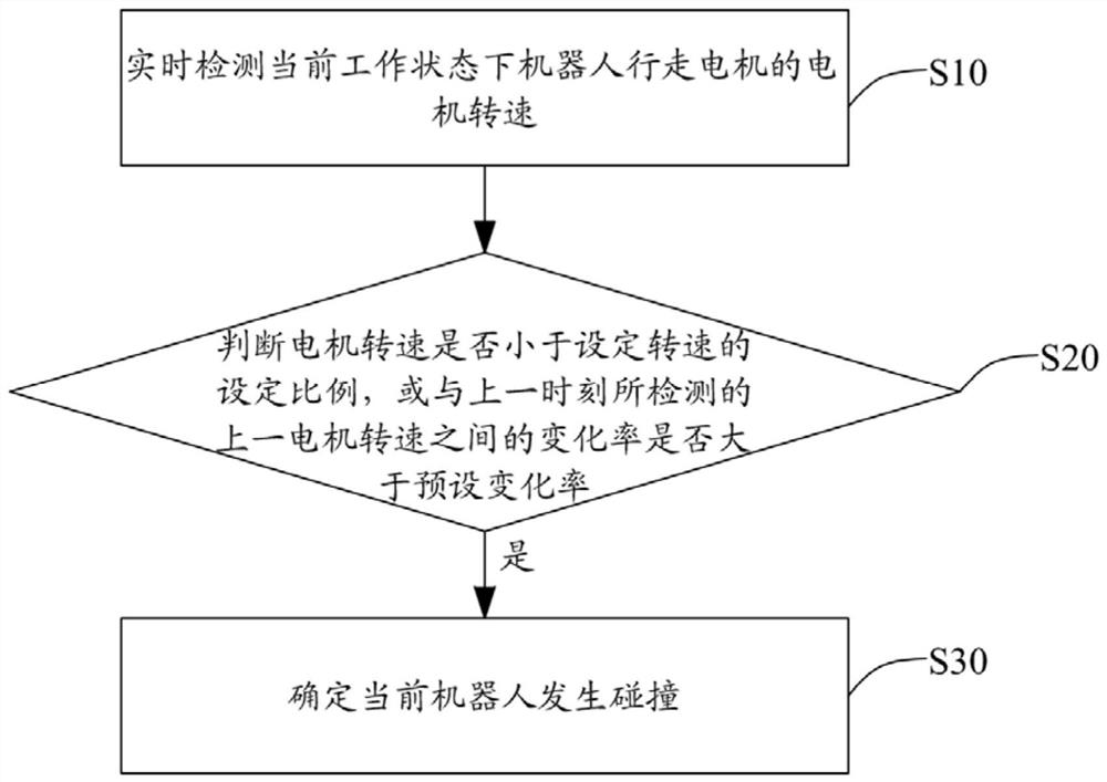
[0044] see figure 1 , is a schematic flowchart of the robot collision detection method provided by the first embodiment of the present invention. For the convenience of description, only the parts related to the embodiment of the present invention are shown. The robot collision detection method includes:
[0045] Step S10, real-time detection of the motor speed of the walking motor of the robot in the current working state;
[0046] Wherein, in one embodiment of the present invention, the robot collision detection method is applied to a robot, specifically in this embodiment, it is applied to a mowing robot, wherein the mowing robot is driven by a motor to realize movement and mowing operations, specifically, In this embodiment, the mowing robot realizes movement by driving the walking motor. At the same time, in order to prevent damage to the motor caused by overcurrent, the robot motor control design generally has a current limiting module to realize current limiting protec...
Embodiment 2
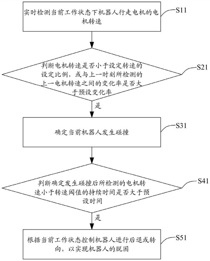
[0057] see figure 2 , is a schematic flowchart of a robot collision detection method provided in the second embodiment of the present invention. For the convenience of description, only the parts related to the embodiment of the present invention are shown. The robot collision detection method includes:
[0058] Step S11, real-time detection of the motor speed of the walking motor of the robot in the current working state.
[0059] Wherein, in one embodiment of the present invention, after the step of detecting the motor speed of the robot in the current working state in real time, it also includes:
[0060] 1. Real-time detection of the motor current of the robot walking motor in the working state;
[0061] 2. Judging the current position area of the robot according to the change state of the motor current;
[0062] 3. Adjust the current limiting threshold of the motor current of the robot walking motor according to the current location area.
[0063] Among them, the la...
Embodiment 3
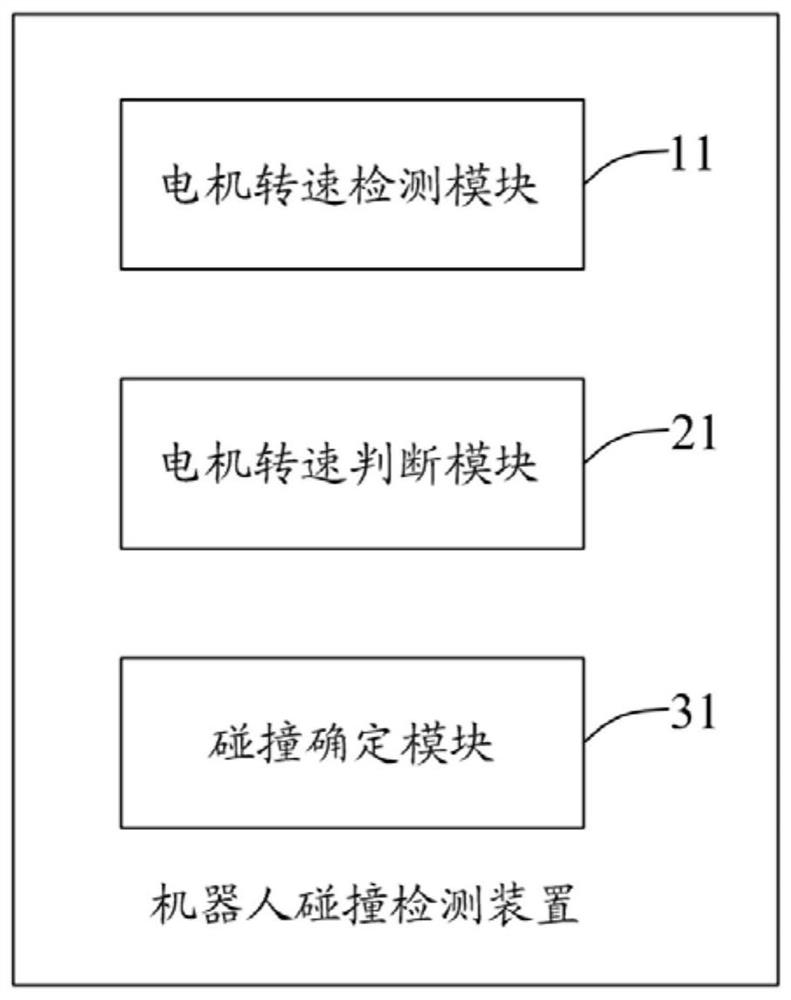
[0082] see image 3, is a schematic diagram of the modules of the robot collision detection device provided by the third embodiment of the present invention. For the convenience of description, only the parts related to the embodiment of the present invention are shown. The robot collision detection device includes:
[0083] The motor speed detection module 11 is used for real-time detection of the motor speed of the robot walking motor in the current working state;
[0084] The motor speed judging module 21 is used to judge whether the motor speed is less than the set ratio of the set speed, or whether the rate of change with the last motor speed detected at the previous moment is greater than the preset rate of change;
[0085] The collision determination module 31 is used for determining that the motor speed judging module 21 is smaller than the set ratio of the set speed, or the rate of change from the previous motor speed detected at the previous moment is greater than th...
PUM
 Abstract
Description
Claims
Application Information