An automatic rotary punching equipment for clothing buttons

An automatic rotation and button technology, applied in metal processing and other directions, can solve the problems of time-consuming, labor-intensive, and unsafe manual drilling.

Active Publication Date: 2022-07-19
沧州明珠服装服饰科技有限公司
View PDF9 Cites 0 Cited by
  • Summary
  • Abstract
  • Description
  • Claims
  • Application Information

AI Technical Summary

Problems solved by technology

[0006] In order to overcome the shortcomings of unsafe, time-consuming and labor-intensive and high cost of manual drilling, the technical problem of the present invention is to provide an automatic rotary punching equipment for clothing buttons that is safe, reliable, time-saving and labor-saving, and can reduce costs.

Method used


Image

  • An automatic rotary punching equipment for clothing buttons
  • An automatic rotary punching equipment for clothing buttons
  • An automatic rotary punching equipment for clothing buttons

Examples


Embodiment 1

[0067] An automatic rotary punching equipment for clothing buttons, such as figure 1 and figure 2As shown, it includes a base plate 1, a first support 2, a cylinder 3, a first push rod 4, a punching mechanism 5 and a discharging mechanism 6. The upper front part of the base plate 1 is provided with two first supports 2, the first The inner side of the support 2 is connected with the cylinder 3, the rear side of the cylinder 3 is provided with a first push rod 4, and the right side of the upper rear of the bottom plate 1 is provided with a punching mechanism 5, which is connected with the first push rod 4, and the bottom plate 1 is provided with a punching mechanism 5 on the right side. The rear part is provided with a discharging mechanism 6 which cooperates with the punching mechanism 5 .

[0068] Manually drilling buttons is unsafe, time-consuming and costly, and this equipment can realize automatic punching, which is safe, reliable, time-saving and labor-saving, and can r...

Embodiment 2

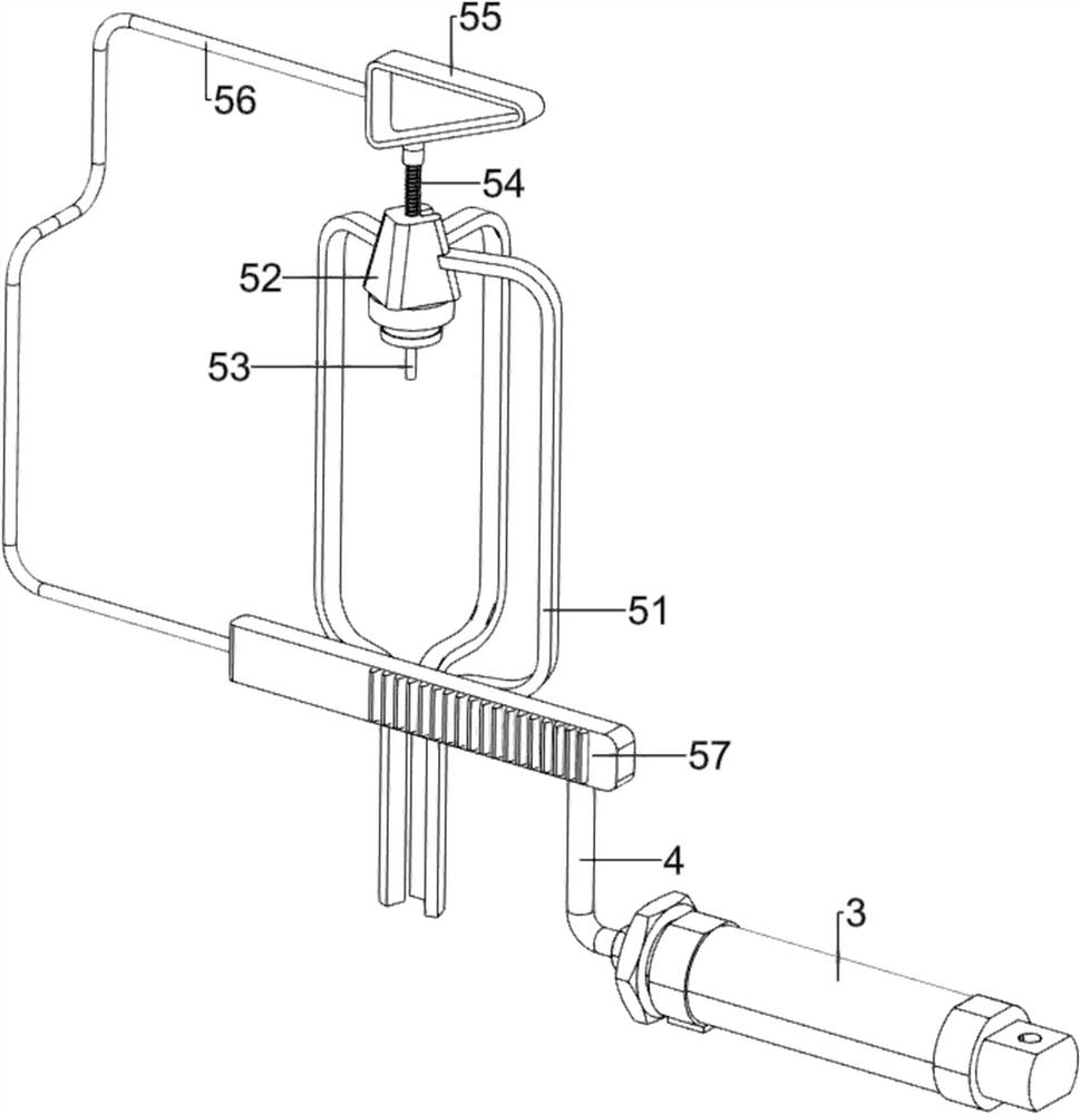
[0070] On the basis of Example 1, as figure 2 , image 3 and Figure 4 As shown, the punching mechanism 5 includes a second support 51, a knife release assembly 52, a punching knife 53, a first spring 54, a first triangular block 55, a first connecting rod 56 and a rack 57. The right side is provided with a second support 51, the upper inner side of the second support 51 is provided with a knife release assembly 52, the inner side of the knife release assembly 52 is slidably provided with a punch knife 53, the punch knife 53 passes through the knife release assembly 52, and the punch knife 53 In cooperation with the feeding mechanism 6, the upper part of the punching knife 53 is surrounded by a first spring 54, the top of the first spring 54 is connected with the first triangular block 55, the bottom of the first spring 54 is connected with the knife-releasing assembly 52, and the top of the first push rod 4 is provided with There is a rack 57, and the rack 57 cooperates wi...

Embodiment 3

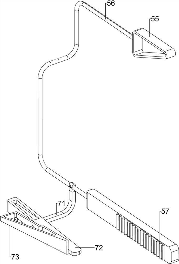
[0075] On the basis of Example 2, as figure 1 , Figure 4 , Figure 5 , Image 6 and Figure 7 As shown, it also includes a driving mechanism 7, the lower part of the first connecting rod 56 is provided with a driving mechanism 7, and the driving mechanism 7 includes a connecting block 71, a second triangular block 72 and a third triangular block 73, and the lower part of the first connecting rod 56 is provided with There is an engaging block 71 , a second triangular block 72 is provided on the left side of the top of the engaging block 71 , and a third triangular block 73 is provided on the left side of the second triangular block 72 .

[0076] When the first connecting rod 56 moves forward, the movement of the first connecting rod 56 drives the connecting block 71 to move forward, the moving block 71 drives the second triangular block 72 to move forward, and the second triangular block 72 drives the third triangular block 73 Moving forward, when the first connecting rod ...


PUM


Abstract

The invention relates to a punching device, in particular to an automatic rotary punching device for clothing buttons. The invention provides an automatic rotary punching device for clothing buttons, which is safe, reliable, time-saving, labor-saving and cost-reduced. An automatic rotary punching device for clothing buttons, comprising: a bottom plate and a first support, the bottom plate is provided with two first supports; an air cylinder, and an air cylinder is connected between the two first supports; a first push rod, The cylinder is provided with a first push rod; the punching mechanism, the bottom plate is provided with a punching mechanism, the punching mechanism is connected with the first push rod; the discharging mechanism, the bottom plate is provided with a discharging mechanism, the discharging mechanism and the punching mechanism Cooperate. In the present invention, the first triangular block cooperates with the punching knife, and the first triangular block exerts pressure on the punching knife, so that the punching knife slides downward in the knife releasing assembly, the first spring changes from the initial state to the compressed state, and the punching knife and the discharging mechanism Cooperate, so as to punch the button, and achieve the effect of automatic punching, which is safe and reliable.

Description

technical field [0001] The invention relates to a punching device, in particular to an automatic rotary punching device for clothing buttons. Background technique [0002] Buttons are an indispensable part of clothing structure. In addition to their practical functions, they also play a finishing touch on the design of clothing. [0003] Buttons can not only connect clothes, keep them tightly insulated, but also make people’s instruments neat and tidy. In button production, drilling has become an essential step in the process. The existing drilling technology is to manually use a metal drill to Drilling a button is time-consuming and labor-intensive, with low work efficiency, high labor cost, and unsafe manual operation. In addition, when the metal drill bit is in contact with the button, if people do not grasp the strength, it is easy to cause the button to break. [0004] Patent application CN203737809U, published on 2014.07.30, discloses a short pipe punching device, inc...

Claims


Application Information

Patent Timeline
Patent Type & Authority Patents(China)
IPC IPC(8): B26F1/14B26D5/12B26D5/22B26D7/06B26D7/32
CPCB26F1/14B26D5/12B26D5/22B26D7/06B26D7/32
Inventor 白彬
Owner 沧州明珠服装服饰科技有限公司
Why Eureka
Try Eureka