A precision printing error proofing equipment for garment production

A precise printing and error-proofing technology, applied in printing, printing machines, printing devices, etc., can solve the problems of easy movement of clothing, inability to fix clothing, offset printing position, etc., to facilitate printing work and prevent printing position offset. Effect

Active Publication Date: 2022-07-19
ZHEJIANG SCI TECH UNIV SHAOXING KEQIAO RES INST CO LTD
View PDF14 Cites 0 Cited by
  • Summary
  • Abstract
  • Description
  • Claims
  • Application Information

AI Technical Summary

Problems solved by technology

[0005] In order to overcome the disadvantages of the above-mentioned patent that the garment cannot be fixed when printing the garment, the garment is easy to move, and the printing position is easily shifted. The technical problem to be solved by the present invention is to provide a method that can fix the garment , a precision printing error-proofing device for garment production that can prevent printing position deviation

Method used


Image

  • A precision printing error proofing equipment for garment production
  • A precision printing error proofing equipment for garment production
  • A precision printing error proofing equipment for garment production

Examples


Embodiment 1

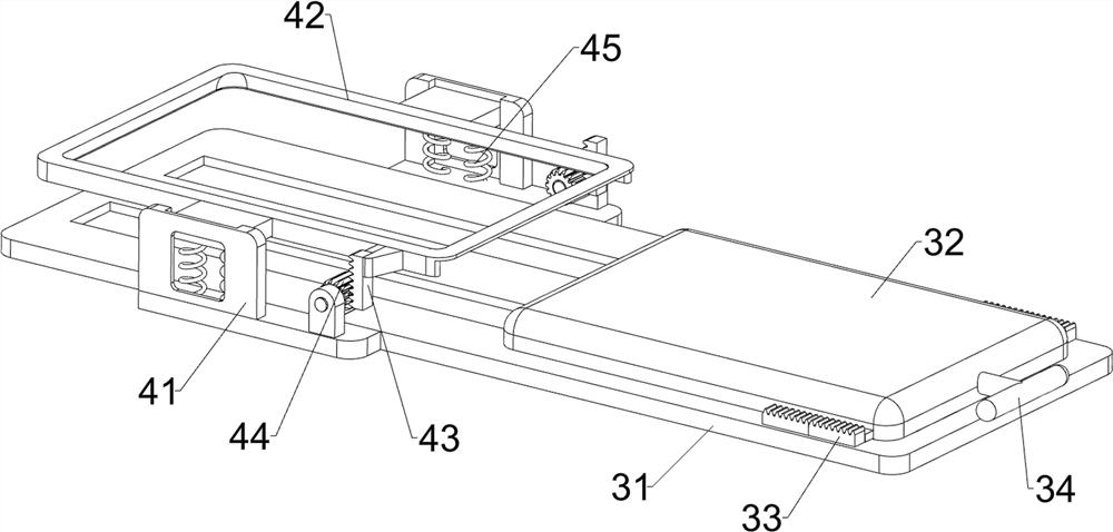
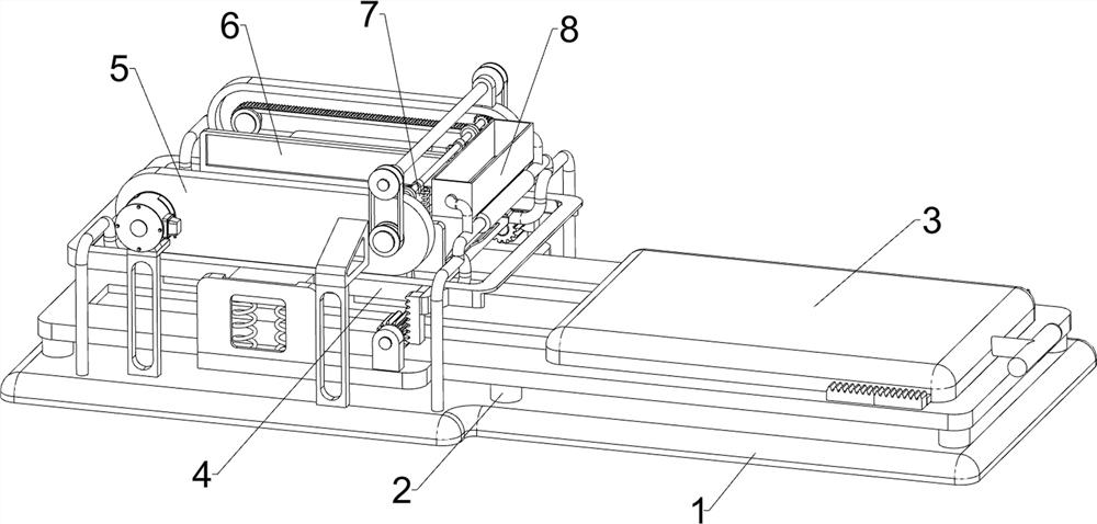
[0027] A precision printing error proofing equipment for garment production, such as figure 1 , figure 2 and Figure 4 As shown, it includes a bottom plate 1, a support column 2, a sliding feed plate mechanism 3, a clamping mechanism 4 and a printing frame mechanism 6. The front and rear sides of the top of the bottom plate 1 are symmetrically connected with a plurality of support columns 2, and a plurality of support columns. A sliding feeding plate mechanism 3 is installed between 2 , a clamping mechanism 4 is installed on the sliding feeding plate mechanism 3 , and a printing frame mechanism 6 is installed on the top of the bottom plate 1 .

[0028] The sliding feeding plate mechanism 3 includes a slotted slide rail plate 31, a placement plate 32, a first gear block 33 and a push rod 34, and a slotted slide rail plate 31 is connected between the top ends of the plurality of support columns 2. The slotted slide rail A placing plate 32 is slidably connected to the plate 31...

Embodiment 2

[0033] On the basis of Example 1, as figure 1 and image 3As shown, a drive mechanism 5 is also included, and the drive mechanism 5 includes a first support frame 51, a guide plate 52, a servo motor 53, a first transmission belt group 54, a rack belt 55, a second transmission belt group 56 and a transmission shaft 57. Two first support frames 51 are connected to the front and rear sides of the left side of the top of the bottom plate 1, a guide plate 52 is connected between the first support frames 51 on the left and right sides, and the top of the first support frame 51 on the left front side is installed with Servo motor 53, a first transmission belt group 54 is rotatably connected to the guide plate 52, the first transmission belt group 54 on the front side is drivingly connected to the servo motor 53, and a rack belt 55 is connected to the belt of the first transmission belt group 54. A transmission shaft 57 is rotatably connected between the top right sides of the two gu...

Embodiment 3

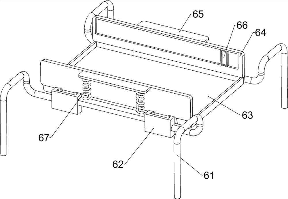
[0037] On the basis of Example 2, as figure 1 and Figure 5 As shown, it also includes a dye replenishing mechanism 8, and the dye replenishing mechanism 8 includes a mounting frame 81, a storage box 82, a guide block 83 and an insert frame 84, and the top right side of the two second support frames 61 is connected with a Mounting frame 81, a storage box 82 is connected to the mounting frame 81, guide blocks 83 are connected to both the front and rear sides of the lower part of the right side of the storage box 82, and a plug-in frame 84 is slidably connected between the two guide blocks 83. The board rack 84 is slidably connected to the storage box 82 .

[0038] The dye can be poured into the storage box 82, and the insert frame 84 can be pulled to the right so that the insert frame 84 does not block the storage box 82, and the dye in the storage box 82 falls on the printing plate 63. After an appropriate amount of dye is dropped on the printing plate 63, the inserting plat...


PUM


Abstract

The invention relates to a printing error-proofing device, in particular to a precise printing error-proofing device for garment production. The invention provides an accurate printing error proofing device for garment production, which can fix the garment during printing and prevent the printing position from shifting. A precision printing error-proofing device for garment production, comprising: a base plate, on which a plurality of support columns are connected; a sliding feeding plate mechanism, a sliding feeding plate mechanism is installed between the supporting columns; a clamping mechanism, which is installed on the sliding feeding plate mechanism There is a clamping mechanism; a printing frame mechanism, and a printing frame mechanism is installed on the bottom plate. In the present invention, the clothing can be transferred to the lower side of the printing frame mechanism through the sliding feeding plate mechanism, and the clothing can be fixed by the clamping mechanism to prevent the clothing from moving during printing, so that the clothing can be fixed during printing, and the printing position can be prevented from shifting. Purpose.

Description

technical field [0001] The invention relates to a printing error-proofing device, in particular to a precise printing error-proofing device for garment production. Background technique [0002] In order to make the clothing more beautiful, it is necessary to print the clothing. After retrieval, the patent publication number is: CN207875172U, which discloses a clothing printing device, including: a printing machine frame, a main drive, an ink jet mechanism and a heat treatment mechanism; the The main drive is arranged through the first end to the second end of the printing machine, the ink jet mechanism is arranged above the first end of the printing machine frame, and the heat treatment mechanism is arranged on the printing machine. Above the middle of the frame; the main drive transmits the garment from its first end to the second end, the inkjet mechanism performs printing work at the first end, and after the printing is completed, the heat treatment mechanism is used for ...

Claims


Application Information

Patent Timeline
Patent Type & Authority Patents(China)
IPC IPC(8): B41F17/00B41F31/04
CPCB41F17/003B41F31/04B41F17/005B41P2217/10
Inventor 蔺慧丽
Owner ZHEJIANG SCI TECH UNIV SHAOXING KEQIAO RES INST CO LTD
Why Eureka
Try Eureka