Intensive retarder

An intensive technology of speed reducers, which is applied to railway car body parts, track brakes, transportation and packaging, etc., can solve the problems of waste of metal resources of spare parts, unfavorable maintenance and repair work, and a large number of speed reducer parts, etc., to achieve improvement Safety performance, convenience for station renovation, and good versatility

Pending Publication Date: 2021-02-26
哈尔滨铁路减速顶调速研究有限公司
View PDF0 Cites 1 Cited by
  • Summary
  • Abstract
  • Description
  • Claims
  • Application Information

AI Technical Summary

Problems solved by technology

[0003] The purpose of the present invention is to solve the problem that the existing deceleration top has a large number of spare parts, which is not conducive to daily maintenance and repair work, the maintenance cost of the station is relatively high, an

Method used


Image

  • Intensive retarder
  • Intensive retarder
  • Intensive retarder

Examples


Example Embodiment

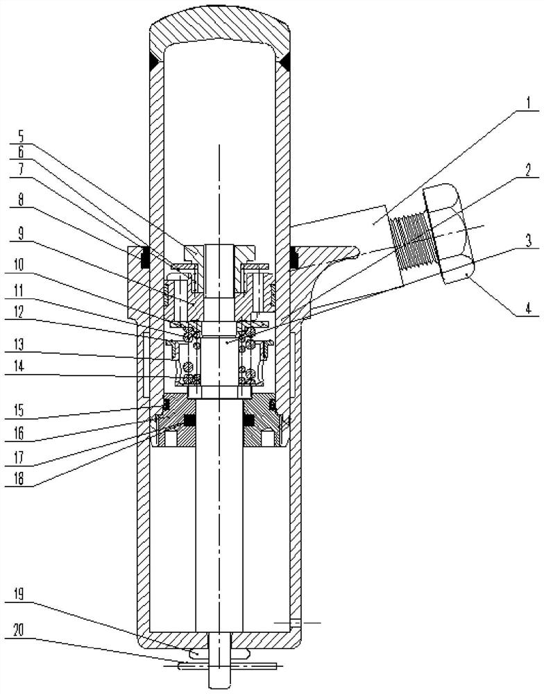
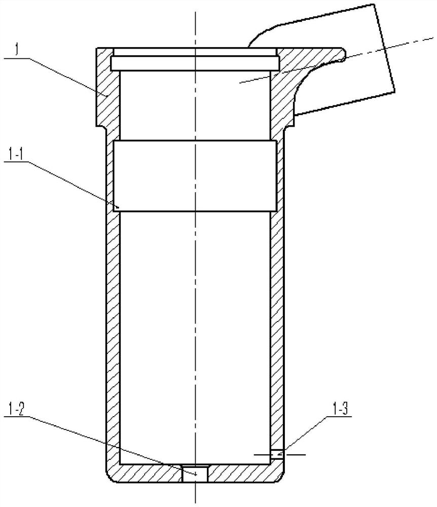
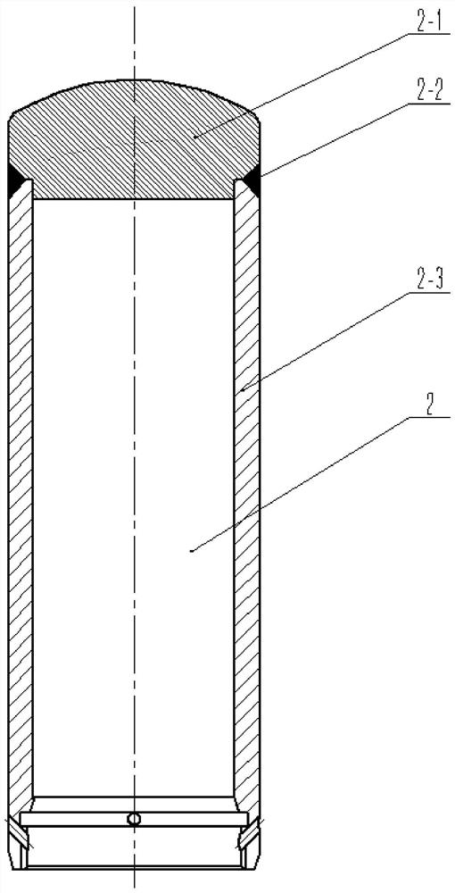
[0024]Specific implementation mode 1: CombinationFigure 1-Figure 5To explain this embodiment, an intensive retarder described in this embodiment includes a housing 1, a sliding cylinder 2, a piston rod 3, a speed valve seat 5, a speed valve plate 6, a speed valve spring 7, and a dust ring 8. , Piston 9, pressure valve plate 10, pressure valve outer spring 11, return valve plate 12, slow return valve plate bracket 13, pressure valve inner spring 14, sealing cover 16 and split pin 20; sealing cover 16 is installed on the sliding cylinder 2 At the bottom end, the piston rod 3 is inserted into the sealing cover 16, the speed valve seat 5, the piston 9, the pressure valve plate 10 and the slow return valve plate bracket 13 are sleeved on the piston rod 3 from top to bottom, and the speed valve The seat 5 is installed on the top of the piston rod 3, the speed valve plate 6 and the speed valve spring 7 are sleeved on the speed valve seat 5, the bottom end of the speed valve seat 5 is insta...

Example Embodiment

[0025]Specific implementation manner two: combinationfigure 1 To explain this embodiment, the intensive type retarder described in this embodiment also includes two hexagon head bolts 4, and each hexagon head bolt 4 is screwed and mounted on the outer side wall of the housing 1. 4 pairs of speed reducers are installed on the inner side of the rail by two hexagon head bolts. Others are the same as the first embodiment.

Example Embodiment

[0026]Specific implementation mode three: combinationfigure 1 To explain this embodiment, the intensive type retarder described in this embodiment also includes a seal 19 which is sleeved on the piston rod 3.

[0027]The seal 19 is an'O'-shaped seal ring 19, which is used to prevent the split pin 20 from breaking during the return stroke of the sliding cylinder 2 and causing the impact stop to fail. Others are the same as the first embodiment.


PUM


Abstract

The invention relates to a retarder, in particular to an intensive retarder, and aims to solve the problems that an existing retarder is large in number of accessory parts, not beneficial to daily maintenance and repair work, high in station maintenance cost, large in pollution discharge capacity in the machining process and prone to polluting the environment, and when the retarder is scrapped, metal resource waste of the accessory parts is serious. The hydraulic retarder comprises a shell, a sliding oil cylinder, a piston rod, a speed valve seat, a speed valve plate, a speed valve spring, a dustproof ring, a piston, a pressure valve plate, a pressure valve outer spring, a return valve plate, a slow return valve plate bracket, a pressure valve inner spring, a sealing cover and a cotter pin. The sealing cover is installed at the bottom end of the sliding oil cylinder, the piston rod is inserted into the sealing cover, the speed valve seat, the piston, the pressure valve plate and the slow return valve plate bracket are arranged on the piston rod in a sleeving mode from top to bottom, and the slow return valve plate bracket is sleeved with the return valve plate. The hydraulic retarder is suitable for a speed regulation device used for railway vehicle humping.

Description

technical field [0001] The invention relates to a deceleration top, in particular to an intensive type deceleration top. Background technique [0002] The speed reducer is an important part of the automatic speed control system of the railway marshalling. It is a speed control device that does not need external energy and automatically controls the rolling speed of railway vehicles. The number of spare parts of the existing retarder products is generally more than 30 pieces, or even more than 40 pieces. The number of spare parts is large, the number of failure links increases, and the difficulty of on-site personnel troubleshooting increases; the variety of spare parts is not conducive to the on-site workers' understanding of the retarder products, nor is it conducive to daily maintenance and repair work; the number of spare parts Many types are not conducive to the management of the station, and the maintenance cost of the station is high; the processing technology of spar...

Claims


Application Information

Patent Timeline
IPC IPC(8): B61K7/02B61K7/08
CPCB61K7/02B61K7/08
Inventor 周际胡东东赵彦凯王潜赵连祥王敬巍王胜军陈峰董小璐郭爽况媛何宁刘柄宏刘聪
Owner 哈尔滨铁路减速顶调速研究有限公司
Why Eureka
Try Eureka