Electric locomotive braking control method and system

A technology for braking control and electric locomotives, which is applied to electric braking systems, electric vehicles, vehicle components, etc., and can solve problems such as commutator damage, wheel scratches, and wheel irregularities

Active Publication Date: 2015-05-06
ZHUZHOU CSR TIMES ELECTRIC CO LTD
View PDF5 Cites 3 Cited by
  • Summary
  • Abstract
  • Description
  • Claims
  • Application Information

AI Technical Summary

Problems solved by technology

However, the large du/dt and di/dt under braking conditions will on the one hand cause the electrical fatigue impact of the motor and the deterioration of the commutation performance. Abnormal wear and tear on the surface of the commutator and brushes acceler...

Method used


Image

  • Electric locomotive braking control method and system
  • Electric locomotive braking control method and system
  • Electric locomotive braking control method and system

Examples


Embodiment 1

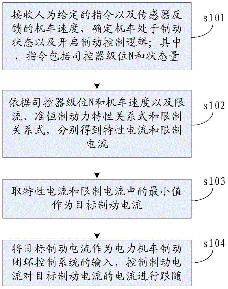
[0047] Please refer to figure 1 , figure 1 It is a flow chart of the process of a braking control method for an electric locomotive provided by the present invention, the method comprising:

[0048] Step s101: Receive the artificially given instruction and the locomotive speed v fed back by the sensor, determine that the locomotive is in the braking state and start the braking control logic; where the instruction includes the controller level N and the state quantity;

[0049] It can be understood that the logic determination module in the control cabinet of the electric locomotive first receives the artificially given command and the locomotive speed v fed back by the locomotive sensor, and determines that the locomotive is in the braking state according to the command and the locomotive speed v, and then the micro-cabinet is opened Brake control logic.

[0050] Step s102: According to the level N of the controller, the speed v of the locomotive, and the current limiting, q...

Embodiment 2

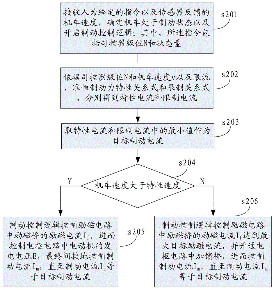
[0138] This embodiment is based on Embodiment 1, please refer to image 3 , image 3 A flow chart of the process of another electric locomotive braking control method provided by the present invention, the method includes:

[0139] Step s201: Receive an artificially given instruction and the locomotive speed fed back by the sensor, determine that the locomotive is in the braking state and start the brake control logic; wherein, the instruction includes the level N of the controller and the state quantity;

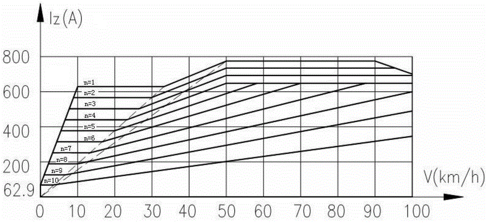
[0140] Step s202: According to the level N of the controller, the speed v of the locomotive, and the current limiting, quasi-constant braking force characteristic relation and limit relation, respectively obtain the characteristic current I 1 and limit the current I 2 ,in:

[0141] The characteristic relation is I 1 = 1197.1 · ...


PUM


Abstract

The invention discloses an electric locomotive braking control method. The method includes the steps of receiving a manually-given instruction and the locomotive speed v fed back by a sensor, determining that a locomotive is in the braked state, and starting the braking control logic, wherein the instruction includes the motorman controller level N and the state amount; obtaining the characteristic current I1 and the limiting current I2 according to the motorman controller level N, the locomotive speed v and the characteristic relational expression and the limiting relational expression of the current-limiting and quasi-constant braking force, and selecting the minimum value in the characteristic current I1 and the limiting current I2 to serve as the target braking current IZ; using the target braking current IZ as the input of an electric locomotive braking closed-loop control system, and controlling the braking current Im to follow the current of the target braking current IZ. The invention further discloses an electric locomotive braking control system. By means of the method and the system, under the periodic locomotive speed sudden change working condition of the electric locomotive, the braking electricity generation voltage and the braking current changes are smoother, the influences of electric impact on an electric motor are effectively eliminated, and meanwhile the reversing performance is optimized and the reverser working environment is improved.

Description

technical field [0001] The invention relates to the technical field of locomotive braking control, in particular to a braking control method and system for an electric locomotive. Background technique [0002] The SS4B type electric locomotive is an 8-axle heavy-duty freight AC-DC electric locomotive developed at the end of the 20th century. It is composed of two identical 4-axle electric locomotives through internal reconnection. The pulse-current motor realizes constant current, quasi-constant speed traction control and traditional current limiting, quasi-constant speed plus feed resistance braking control through micro-cabinet phase control and voltage regulation. [0003] When the SS4B electric locomotive is going downhill on a long slope, its electric braking force cannot meet the braking requirements of heavy-duty trains, and the crew needs to frequently use the air brake to reduce the speed. For example, when a SS4B electric locomotive pulls a 5000t class heavy-duty ...

Claims


Application Information

Patent Timeline
IPC IPC(8): B60L7/22
Inventor 陈灿郭建姚晓东蔡杰刘灿李鹏李状欧阳天添李龙标
Owner ZHUZHOU CSR TIMES ELECTRIC CO LTD
Why Eureka
Try Eureka