Vehicular brake control device

a technology of brake control device and brake plate, which is applied in the direction of brake systems, etc., can solve the problems of unstable braking force on right and left wheels, risk of further complication of hydraulic circuit configuration, etc., and achieve the effect of simple configuration, gradual increase or decrease of pressure on all wheels

Inactive Publication Date: 2006-01-26
ADVICS CO LTD
View PDF7 Cites 4 Cited by
  • Summary
  • Abstract
  • Description
  • Claims
  • Application Information

AI Technical Summary

Benefits of technology

[0031] Note that by using linear valves to form the third and second electromagnetic opening/closing valves, it is possible to gradually increase or decre...

Problems solved by technology

Therefore, in addition to complicating the valve configuration of the vehicular brake control device, there is a risk of further complication in the configuration of the hydraulic circuit.
Accordingly, there is a ...

Method used


Image

  • Vehicular brake control device
  • Vehicular brake control device
  • Vehicular brake control device

Examples


first embodiment

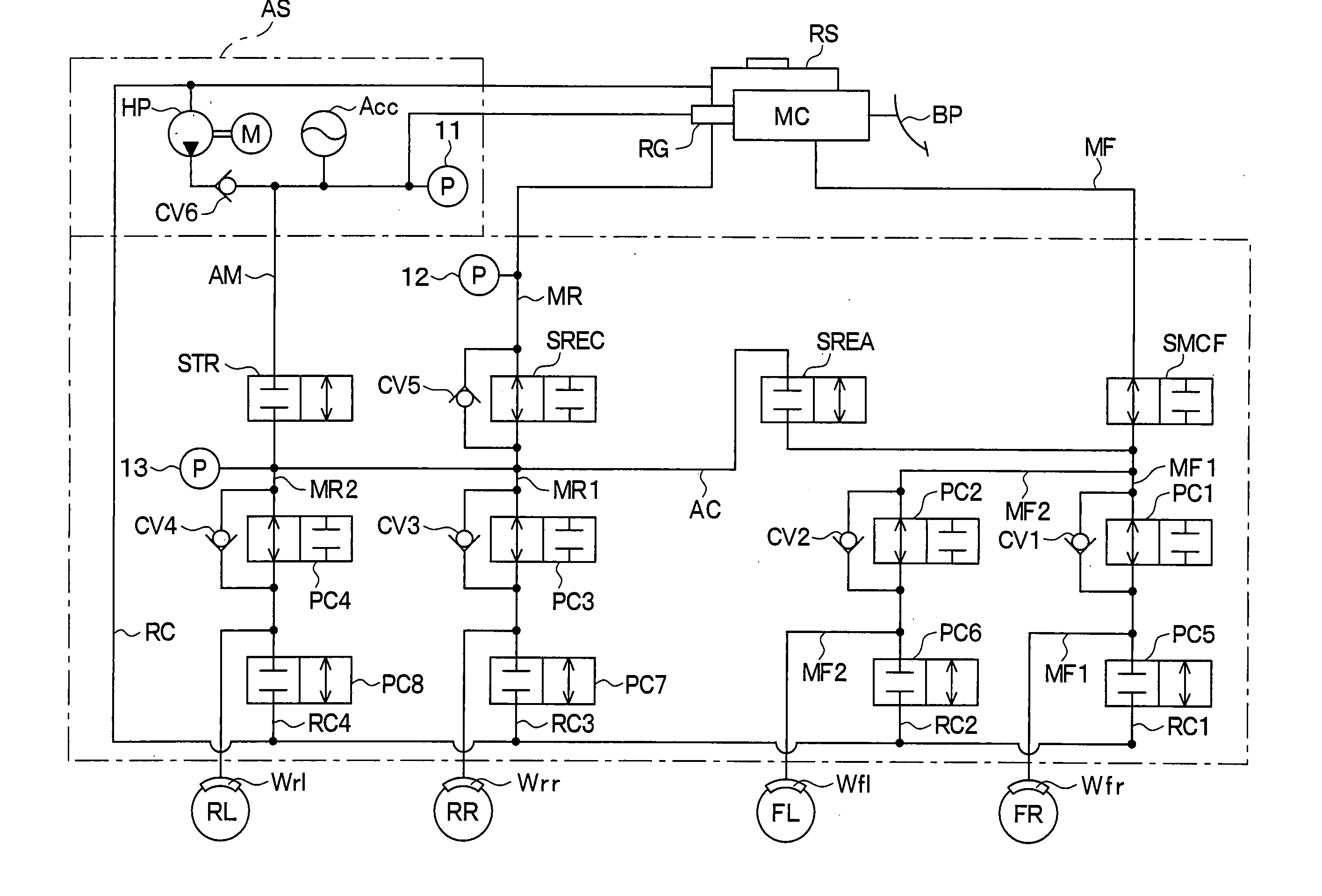
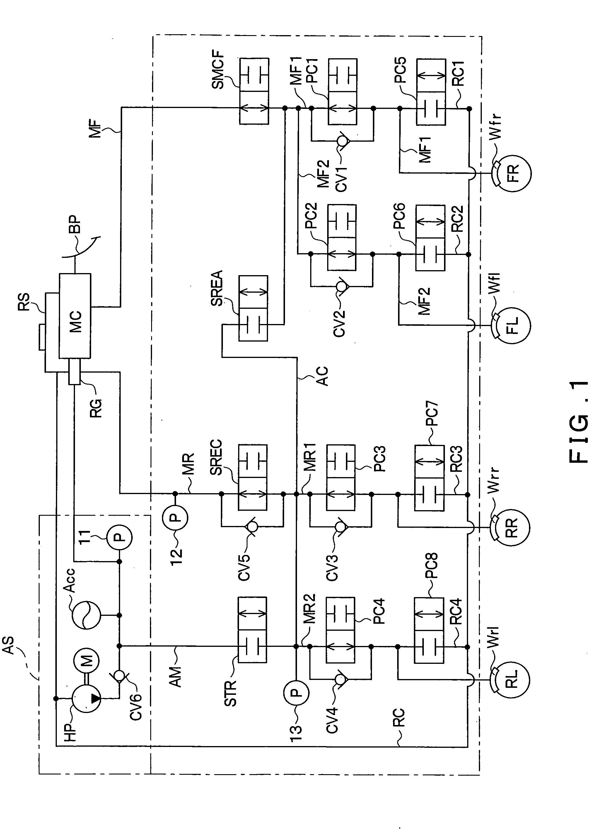
[0038]FIG. 1 shows a hydraulic circuit configuration of a vehicular brake control device to which an embodiment of the present invention is applied. Hereinbelow, the configuration of a vehicular brake control device according to the present embodiment will be described with reference to the figure.

[0039] As shown in FIG. 1, the vehicular brake control device is provided with a master cylinder MC and a regulator RG, which are both driven in accordance with the operation of a brake pedal BP. The regulator RG is connected to an auxiliary hydraulic pressure source AS. The auxiliary hydraulic pressure source AS and the master cylinder MC are both connected to a low-pressure reservoir RS.

[0040] The auxiliary hydraulic pressure source AS is provided with a hydraulic pump HP and an accumulator Acc. The hydraulic pump HP is driven by an electric motor M, whereby brake fluid is sucked in and discharged from the low-pressure reservoir RS. Brake fluid discharged from the hydraulic pump HP is ...


PUM


Abstract

A master cylinder MC is connected to wheel cylinders via brake conduits, and electromagnetic opening/closing valves configured as two-position valves with two ports are provided in the brake conduits, respectively. A brake conduit connects an area among a brake conduit between an electromagnetic opening/closing valve and pressure increase control valves with an area among another brake conduit between another electromagnetic opening/closing valve and pressure increase control valves. The brake conduit therebetween is provided with an electromagnetic opening/closing valve formed from a two-position valve with two ports. By using such a configuration, various controls can be executed as required in the event of an emergency, in addition to normal braking including automatic braking.

Description

CROSS REFERENCE TO RELATED APPLICATION [0001] This application is based upon and claims the benefit of Japanese Patent Application No. 2004-214433 filed on Jul. 22, 2004, the content of which are incorporated herein by reference. FIELD OF THE INVENTION [0002] The present invention relates to a vehicular brake control device provided with a regulator. BACKGROUND OF THE INVENTION [0003] A related vehicular brake control device provided with a regulator is disclosed in Japanese Patent Laid-Open Publication No. HEI 11-139273. FIG. 4 shows the configuration of a hydraulic circuit in the related vehicular brake control device. [0004] As shown in the figure, the vehicular brake control device is provided with a master cylinder MC and a regulator RG, which are both driven in accordance with the operation of a brake pedal BP. The regulator RG is connected to an auxiliary hydraulic pressure source AS. Along with the master cylinder MC, both are connected to a low-pressure reservoir RS. [0005]...

Claims


Application Information

Patent Timeline
IPC IPC(8): B60T8/40
CPCB60T8/4072B60T8/348
Inventor KOJIMA, SEIICHISAKATA, YASUNORITAKEUCHI, KIYOHITO
Owner ADVICS CO LTD
Why Eureka
Try Eureka