

Elevator provided with emergency braking device
An emergency braking and elevator technology, which is applied in transportation, packaging, elevators, etc., can solve the problems of buffer body loss of shock absorption, buffer body deformation change, lack of reproducibility, etc., to achieve convenient positioning, restrain rebound, and improve stability sexual effect
- Summary
- Abstract
- Description
- Claims
- Application Information
AI Technical Summary
Problems solved by technology
Method used
Image

Examples
Embodiment Construction
[0042] The emergency braking device in the elevator of the present invention will be described below with reference to the accompanying drawings.
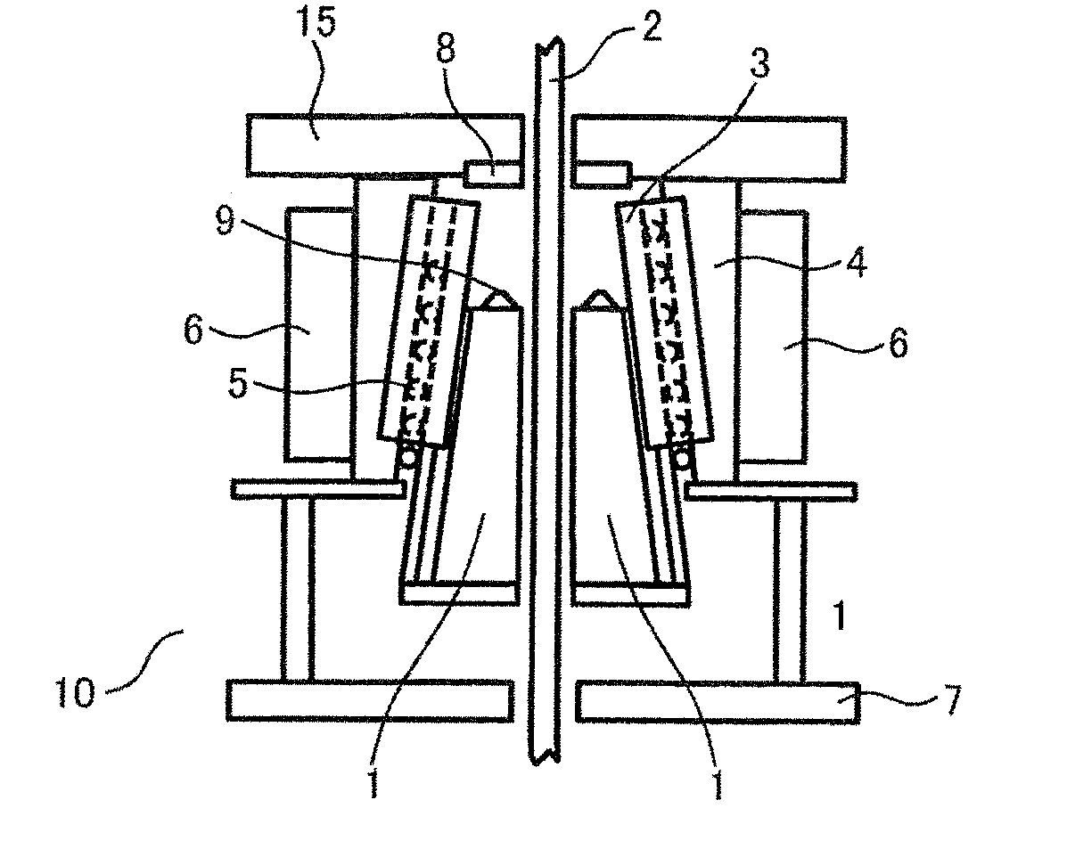
[0043] figure 1 It is a longitudinal sectional view when the emergency braking device 10 is not operating (the elevator is running normally).
[0044] The emergency brake device 10 has a pair of brake shoes 1 arranged bilaterally symmetrically across the guide rail 2 , and the pair of brake shoes 1 are arranged substantially parallel to the guide rail 2 with a slight gap therebetween so as to sandwich the guide rail 2 .
[0045] The back surface of the brake shoe 1 opposite to the guide rail is a smooth inclined surface having a wedge shape that narrows upward.
[0046] In order to move the brake shoe 1 to a predetermined position, a guide member 4 for guiding the displacement of the brake shoe 1 is provided on the back surface of the brake shoe 1 .
[0047] The guide member 4 has a guide plate 3 and a roller 5. The inner side of...
PUM
 Abstract
Description
Claims
Application Information