
Bicycle pedal structure

A technology for bicycles and pedals, which is applied to vehicle components, rider driving, transportation and packaging, etc. It can solve problems such as high cost, troublesome processing, and pedals that cannot be used normally, and achieves simple production, low cost, and less prone to problems Effect

Pending Publication Date: 2021-02-26
FUJIAN KUNFU +2
View PDF0 Cites 0 Cited by
  • Summary
  • Abstract
  • Description
  • Claims
  • Application Information

AI Technical Summary

Problems solved by technology

[0003] Existing pedals include a pedal and a mandrel; a bearing is respectively provided at both ends of the center of the pedal, and one end of the mandrel passes through the center of the pedal and the two bearings for fixing, and the other end of the mandrel is provided with a threaded column, which is connected with the crank on the crank. The threaded port is connected and fixed, so the pedal can rotate freely around the mandrel; this structure has the following problems: first, the pedal structure leads to relatively troublesome processing and high cost; second, two bearings are required, which increases the cost and damage Rate (any bearing damage will cause the pedal to not work normally)

Method used


Image

  • Bicycle pedal structure
  • Bicycle pedal structure
  • Bicycle pedal structure

Examples


Embodiment Construction

[0016] In order to make the object and technical solutions of the present invention clearer, the present invention will be further described below in conjunction with the accompanying drawings and embodiments:

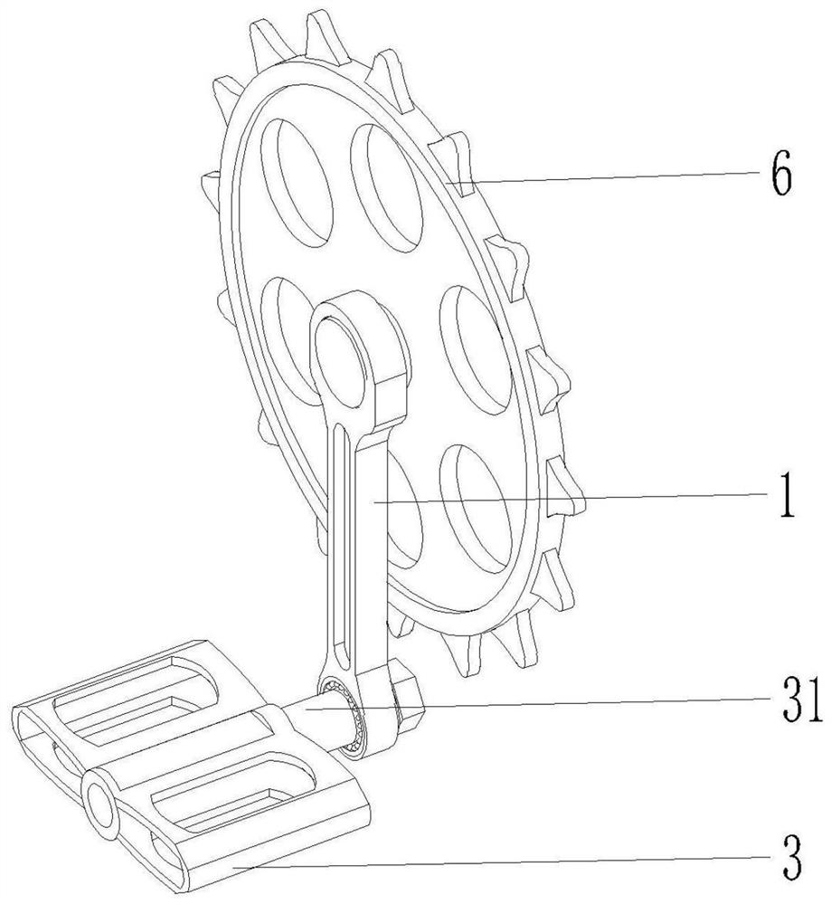
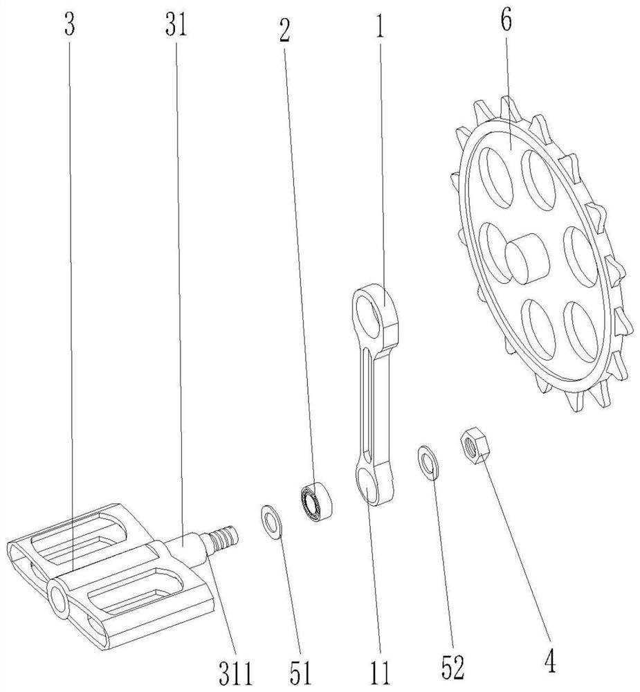
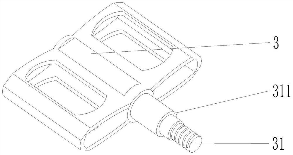
[0017] like Figure 1 ~ Figure 3 A bicycle pedal structure shown includes a crank 1; the upper end of the crank 1 is fixedly mounted on the toothed plate 6 of the bicycle, and a mounting hole is provided below the crank 1, and the mounting hole forms a bearing seat 11; the bearing 2, Installed in the bearing seat 11; the pedal structure is integrally formed, including: a pedal 3; a mandrel 31 is arranged in the middle of the pedal; the pedal 3 is installed and fixed on the bearing through the mandrel 31 2 on.

[0018] Bearing 2 can be installed in described bearing seat 11 (not shown in the figure) through end cap, and mandrel 31 and bearing 2 are interference fit, and this assembly method is more inconvenient when replacing pedal later.

[0019] Preferably, the bear...


PUM


Abstract

The invention provides a bicycle pedal structure. The bicycle pedal structure comprises a crank, wherein a mounting hole is formed in the lower part of the crank and forms a bearing seat; a bearing, which is mounted in the bearing seat; and a pedal structure, which is an integrally-formed whole and comprises a pedal. A mandrel is arranged in the middle of the pedal; the pedal is mounted and fixedon the bearing through the mandrel; the bearing is in interference fit with the bearing seat; the mandrel penetrates through the inner ring of the bearing; the mandrel is provided with a top ring, andthe top ring is used for fixing the inner ring of the bearing; the tail part of the mandrel is provided with a thread, and the mandrel is fixedly arranged on the inner ring of the bearing by screwingin a nut and matching with the top ring; compared with an original double-bearing structure, only one bearing is needed, the cost is reduced, and the risk of problems is reduced; in addition, the pedal is integrally formed, mold opening and manufacturing are easier, the cost is reduced, the pedal is firm and durable due to integral forming, and problems are not prone to occurring.

Description

technical field [0001] The invention relates to a bicycle pedal structure. Background technique [0002] The pedal structure of the bicycle is assembled on the left and right cranks of the central shaft component. When the bicycle is riding, the pedal force is first transmitted to the pedal structure, and then the pedal shaft turns the crank, crankshaft, central shaft, and chain flywheel to make the rear The wheel rotates to make the bicycle move forward; therefore, whether the structure and specifications of the pedals are appropriate will directly affect whether the rider's foot position is appropriate and whether the bicycle can be driven smoothly. The pedal plane is constantly changing, which makes the pedals must rotate flexibly. [0003] Existing pedals include a pedal and a mandrel; a bearing is respectively provided at both ends of the center of the pedal, and one end of the mandrel passes through the center of the pedal and the two bearings for fixing, and the othe...

Claims


Application Information

Patent Timeline
IPC IPC(8): B62M1/38
CPCB62M1/38
Inventor 石秉钧王铭君
Owner FUJIAN KUNFU
Learn More