
Sliding rail used in cooperation with conveying mechanism

A conveying mechanism and fluent strip technology, which is applied in the field of fluent strips, can solve the problems of inconvenient cleaning, easy sticking of guide pulleys with more dust, stone particles, and fluent strip structure stuck in normal use, etc., to achieve the effect of ensuring the cleaning effect

Active Publication Date: 2021-02-26
宿迁国发科技有限公司
View PDF7 Cites 1 Cited by
  • Summary
  • Abstract
  • Description
  • Claims
  • Application Information

AI Technical Summary

Problems solved by technology

[0004] In order to overcome the above-mentioned defects of the prior art, the present invention provides a fluent strip used in conjunction with a conveying mechanism. The technical problem to be solved by the present invention is: when the fluent strip is used for a long time, its guide pulley tends to stick There are a lot of dust and stone particles, and the existing fluent strips are usually not easy to clean them, or some fluent strips can vacuum the sticky dust, but they cannot clean more impurity particles, such as The stones are effectively cleaned, but it is easy to cause the structure of the fluent strip to get stuck and affect its normal use.

Method used


Image

  • Sliding rail used in cooperation with conveying mechanism
  • Sliding rail used in cooperation with conveying mechanism
  • Sliding rail used in cooperation with conveying mechanism

Examples


Embodiment Construction

[0028] The following will clearly and completely describe the technical solutions in the embodiments of the present invention with reference to the accompanying drawings in the embodiments of the present invention. Obviously, the described embodiments are only some, not all, embodiments of the present invention. Based on the embodiments of the present invention, all other embodiments obtained by persons of ordinary skill in the art without making creative efforts belong to the protection scope of the present invention.

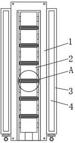
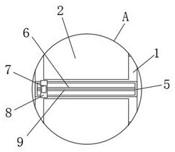
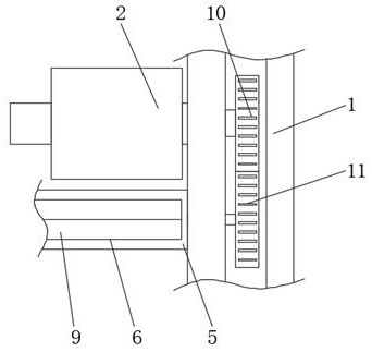
[0029] Such as Figure 1-7 As shown, the present invention provides a fluent strip used in conjunction with a conveying mechanism, including a fluent strip 1, a plurality of guide pulleys 2 are arranged inside the fluent strip 1, and the left and right ends of the guide pulleys 2 are respectively clamped on the inner wall of the fluent strip 1. On the left and right sides, the fluent strip 1 is provided with several cleaning mechanisms 5, the left and right si...


PUM


Abstract

The invention discloses a sliding rail used in cooperation with a conveying mechanism, and particularly relates to the technical field of logistics equipment. The sliding rail comprises a sliding railbody, and a plurality of guide pulleys are arranged in the sliding rail body; the right and left ends of each guide pulley are connected with the right and left side faces of the inner wall of the sliding rail body in a clamped mode separately; and a plurality of cleaning mechanisms are arranged in the sliding rail body. According to the sliding rail, through meshing of a first gear and a secondgear, when goods are pulled to move on the sliding rail, a guide screw rod can be linked to rotate synchronously; through the connecting effect of a threaded sleeve block, a cleaning push plate can bedriven by the guide screw rod to move, thereby facilitating automatic cleaning of large-particle impurities between the guide pulleys; the guide pulleys are easily driven to reversely rotate to drivethe cleaning push plate to reset while the goods are pushed. Compared with a traditional sliding rail, the sliding rail has the advantages that large impurities in the sliding rail can be automatically removed while the goods are conveyed through cooperation of the sliding rail, and the situation that the sliding rial is jammed by the large impurities and consequently the normal use of the sliding rail is affected is effectively avoided.

Description

technical field [0001] The invention relates to the technical field of logistics equipment, and more specifically, the invention relates to a fluent strip used in conjunction with a conveying mechanism. Background technique [0002] Fluent bar is the abbreviation of aluminum alloy slide rail. Because of its convenient and quick installation, the items placed above run smoothly and neatly, so it is called fluent bar as the name suggests. It is mostly used for material racks in workshops, etc. [0003] The Chinese patent document CN201910497989.4 discloses a fluent strip for conveying. In the scheme, it is recorded that "it includes a long box body and a roller wheel that is rotatably arranged in the box body. Cloth, a partition is formed on the inner wall of the box, and the partition divides the inner cavity of the box into an upper cavity and a lower cavity. The length of the mouth extends along the length of the box body. The lower side of the roller is in the dust coll...

Claims


Application Information

Patent Timeline
Patent Type & Authority Applications(China)
IPC IPC(8): B65G13/04B65G45/10
CPCB65G13/04B65G45/10
Inventor 李传之
Owner 宿迁国发科技有限公司
Learn More