Wharf structure

A dock and silt technology, applied in the field of water conservancy engineering, can solve the problems of high cost, inability to dredging at any time, affecting the normal operation of the dock, etc., and achieve the effect of timely dredging

Inactive Publication Date: 2021-02-26
CHINA HARBOUR ENGINEERING
View PDF5 Cites 0 Cited by
  • Summary
  • Abstract
  • Description
  • Claims
  • Application Information

AI Technical Summary

Problems solved by technology

Dredgers are usually used for dredging, but the dredgers will affect the normal operation of the terminal, and dredging cannot be carried out at any time, and there is also a problem of high cost

Method used


Image

  • Wharf structure
  • Wharf structure

Examples


Embodiment Construction

[0021] The present invention will be further described in detail below in conjunction with the accompanying drawings, so that those skilled in the art can implement it with reference to the description.

[0022] It should be understood that terms such as "having", "comprising" and "including" used herein do not exclude the presence or addition of one or more other elements or combinations thereof.

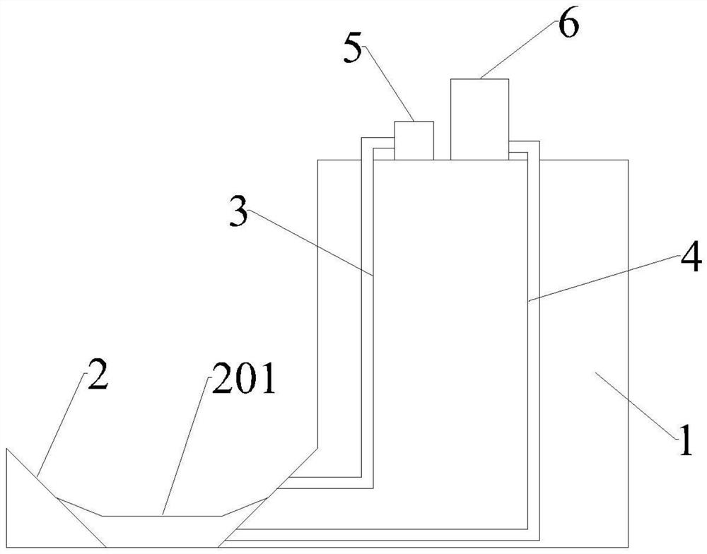
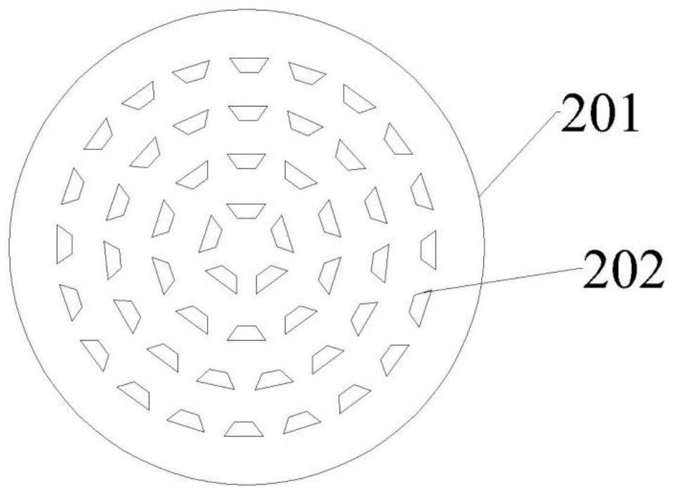
[0023] Such as figure 1 , 2 As shown, the embodiment of the present application provides a wharf structure, including: a wharf main body 1; a silt tank 2, which is arranged at the bottom of the front of the wharf main body 1, and a partition 201 is arranged above the bottom of the silt tank 2, and the partition 201 divides the silt tank 2 into a first part located above and a second part located below, fish scale holes 202 are distributed on the surface of the partition 201, and suction holes are provided on the side wall of the first part of the silt tank 2. Mud port, the side w...


PUM


Abstract

The invention discloses a wharf structure. The wharf structure comprises a wharf body, a sludge tank, a filtering mechanism, a water collecting tank, and a controller; the sludge tank is arranged at the bottom in front of the wharf body; a partition plate is arranged above the bottom of the sludge tank and divides the sludge tank into a first part located above and a second part located below; scale holes are distributed in the surface of the partition plate; a sludge suction port is formed in the side wall of the first part of the sludge tank; a water spraying opening is formed in the side wall of the second part of the sludge tank; a water inlet of the filtering mechanism is communicated with the sludge suction port through a sludge suction pipe, and a sludge pump is arranged on the sludge suction pipe; the water collecting tank is communicated with the water outlet of the filtering mechanism, the water collecting tank is further communicated with the water spraying opening through awater spraying pipe, and a high-pressure water pump is arranged on the water spraying pipe; and the controller is electrically connected with the sludge suction pump and the high-pressure water pumpand controls the high-pressure water pump and the sludge suction pump to be switched between a first working mode and a second working mode. According to the wharf structure, the use of the sludge suction pumping ship can be reduced, and desilting work can be automatically carried out as required.

Description

technical field [0001] The invention relates to the technical field of hydraulic engineering. More specifically, the present invention relates to a wharf structure. Background technique [0002] A wharf is a hydraulic structure for ships to dock, load and unload goods, and passengers. During the operation of the wharf, a lot of silt will be deposited on its channel and edge along with the movement of the water flow, so the wharf must be frequently desilted. Dredgers are usually used for dredging, but dredgers will affect the normal operation of the wharf, and dredging cannot be performed at any time, and there is also a problem of high cost. Therefore, there is an urgent need to design a technical solution that can overcome the above-mentioned defects. Contents of the invention [0003] An object of the present invention is to provide a wharf structure that reduces the use of dredgers and can automatically perform dredging work as needed. [0004] In order to achieve t...

Claims


Application Information

Patent Timeline
Patent Type & Authority Applications(China)
IPC IPC(8): E02B3/06
CPCE02B3/068Y02A10/11
Inventor 熊洪峰
Owner CHINA HARBOUR ENGINEERING
Why Eureka
Try Eureka