Nutrition bowl auxiliary soil covering device for plant cultivation
A plant cultivation and nutrition bowl technology, which is applied to the field of auxiliary soil-covering devices for plant cultivation using a nutrition bowl, can solve problems such as arm work and unbalanced loading, and achieve the effects of improving work efficiency and realizing dredging operations.
- Summary
- Abstract
- Description
- Claims
- Application Information
AI Technical Summary
Problems solved by technology
Method used
Image
Examples
Embodiment 1
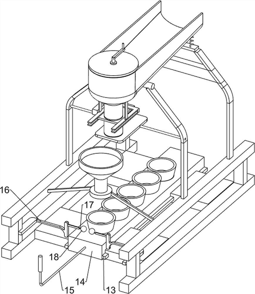
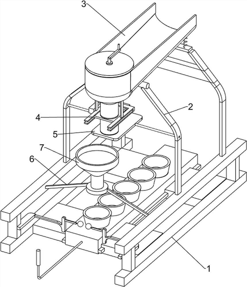
[0027] Such as figure 1 , figure 2 and image 3 As shown, an auxiliary soil-covering device for a nutritional bowl for plant cultivation includes a base 1, a support 2, a charging device 3, a quantitative feeding device 4, a baffle 5, a support frame 6 and a hopper 7, and the top of the base 1 is symmetrically arranged with Two brackets 2 and four brackets 2 are provided with a charging device 3, and a quantitative feeding device 4 is arranged between the two brackets 2 on the front side. The quantitative feeding device 4 cooperates with the charging device 3, and the two brackets 2 on the front side A baffle 5 is arranged between them, and the baffle 5 cooperates with the quantitative feeding device 4 . The top of the base 1 is symmetrically provided with a support frame 6 , and an inverted hopper 7 is arranged between the support frames 6 , and the inverted hopper 7 is located at the lower side of the quantitative feeding device 4 .
[0028] The charging device 3 includes...
Embodiment 2
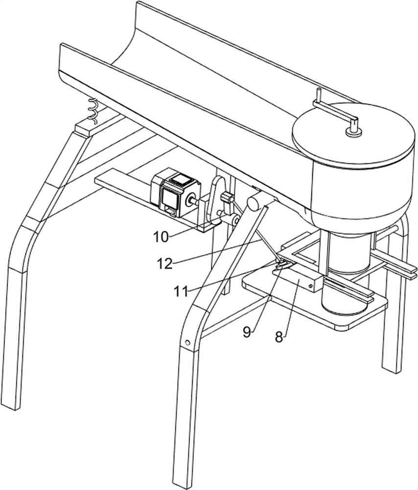
[0032] Such as Figure 4 and Figure 5 and Figure 6 As shown, on the basis of Embodiment 1, it also includes a mounting block 8, a ball bearing seat 9, a crank 10, a rotating ball 11 and a connecting rod 12, and the moving rod 46 is provided with a mounting block 8, and the slope of the mounting block 8 A ball bearing seat 9 is provided at the position, a crank 10 is provided at the end of the first rotating shaft 34, a rotating ball 11 is arranged on the crank 10 and the ball bearing seat 9, and a connecting rod 12 is arranged between the two rotating balls 11.
[0033] The rotating motor 36 drives the first rotating shaft 34 to rotate, and at the same time that the cam 35 can vibrate and transfer materials to the unloading chute 31, it can also drive the crank 10 to perform a circular motion, and the crank 10 drives the mounting block 8 through the rotating ball 11 and the connecting rod 12. Moving back and forth, the mounting block 8 can drive the moving rod 46 to move f...
PUM
 Abstract
Description
Claims
Application Information
 - R&D
- Intellectual Property
- Life Sciences
- Materials
- Tech Scout
- Unparalleled Data Quality
- Higher Quality Content
- 60% Fewer Hallucinations
Browse by: Latest US Patents, China's latest patents, Technical Efficacy Thesaurus, Application Domain, Technology Topic, Popular Technical Reports.
© 2025 PatSnap. All rights reserved.Legal|Privacy policy|Modern Slavery Act Transparency Statement|Sitemap|About US| Contact US: help@patsnap.com


