Receiving and transferring device for mixed garbage
A technology of transfer device and garbage transfer vehicle, which is applied in the direction of garbage receptacle, transportation and packaging, etc. It can solve the problems of garbage corruption, time-consuming and laborious, laborious operation, etc., and achieve the effect of increasing storage capacity, convenient use and multiple functions
- Summary
- Abstract
- Description
- Claims
- Application Information
AI Technical Summary
Problems solved by technology
Method used
Image
Examples
Embodiment 1
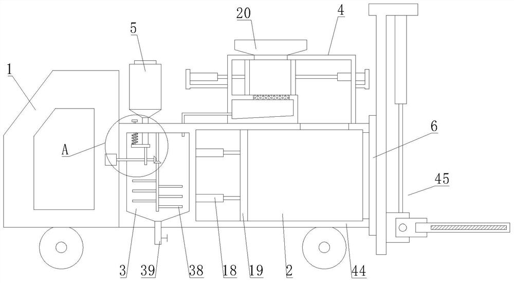
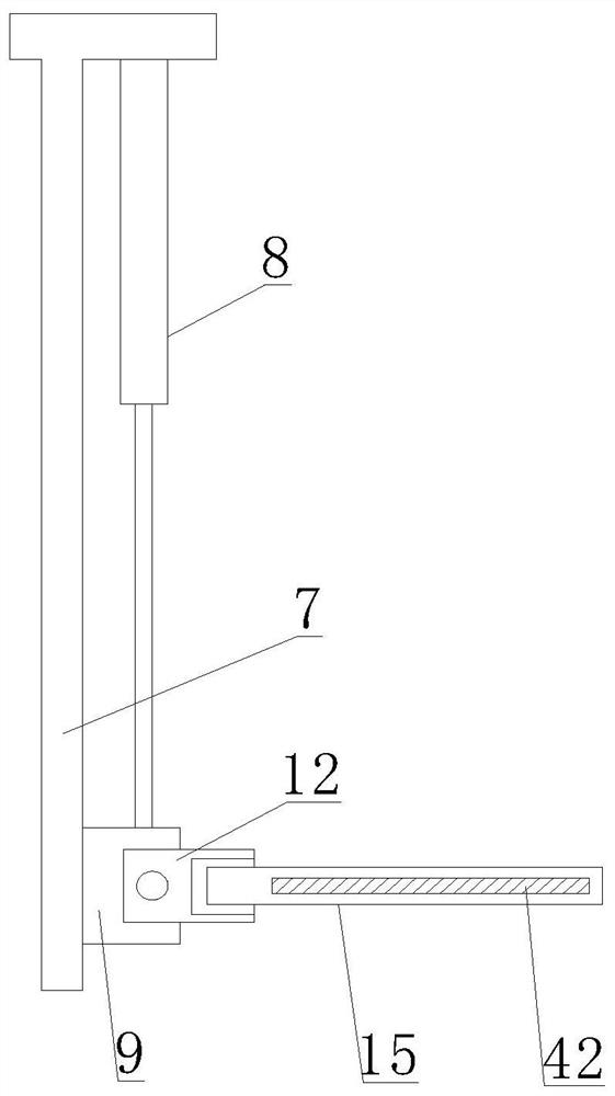
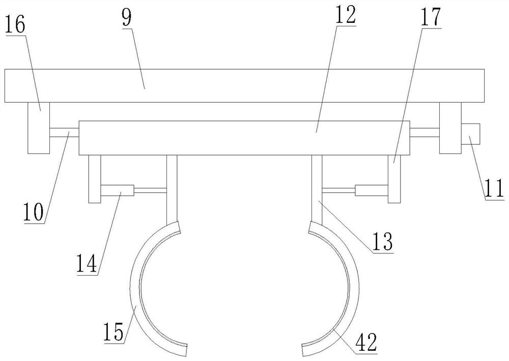
[0029] Such as Figure 1-4As shown, a receiving and transferring device for mixed garbage proposed by the present invention includes a garbage transfer vehicle 1, a sealed door 6 and a compartment 44, the compartment 44 is arranged on the garbage transfer vehicle 1, and the compartment 44 is used for loading garbage. The compartment 44 is provided with a garbage storage cavity 2, which stores solid waste. The airtight door 6 is hinged on the compartment 44 through a hinge, and the airtight door seals the opening of the compartment 44. The compartment 44 is provided with The third cylinder 18 and the push plate 19, and the push plate 19 is located between the airtight door 6 and the third cylinder 18, the other end of the third cylinder 18 is fixedly connected with the push plate 19 by bolts; the top of the compartment 44 is fixed by bolts A solid-liquid separation box 4 is installed, and the top of the solid-liquid separation box 4 is fixedly provided with a feed hopper 20; a ...
Embodiment 2
[0032] Such as Figure 5 As shown, this embodiment is basically the same as Embodiment 1. Preferably, the solid-liquid separation box 4 is provided with an extrusion chamber 21, a discharge chamber 22 and a liquid discharge chamber 23, and the extrusion chamber 21 and the discharge chamber 22 Located on both sides of the interior of the solid-liquid separation box 4, the liquid discharge chamber 23 is located below the extrusion chamber 21; the discharge chamber 22 communicates with the garbage storage chamber 2, the infusion tube 29 communicates with the liquid discharge chamber 23, and the liquid discharge The liquid in the chamber 23 is output through the infusion tube 29, the feed hopper 20 is located above the extrusion chamber 21, and the garbage enters the extrusion chamber 21 through the feed hopper 20; the solid-liquid separation box 4 is horizontally installed by bolts There is a filter plate 24, and the filter plate 24 separates the extrusion chamber 21 and the liqu...
Embodiment 3
[0034] Such as figure 1 and Figure 6 As shown, this embodiment is basically the same as Embodiment 1. Preferably, a second motor 31 is fixedly installed on the compartment 44 through a motor base, and the output end of the second motor 31 is provided with a second rotating shaft 32. The motor 31 is used to drive the second rotating shaft 32; the blocking block 43 is located below the feed pipe 30 and seals the outlet of the feed pipe 30, the guide rod 36 is vertically arranged on the block block 43, and the guide rod 36 passes upwards Compartment 44 is also connected to limit block 37, and spring 35 is sleeved on the guide rod 36 and is connected to compartment 44 and blocking block 43; Cam 33 is installed on the described second rotating shaft 32 by bolt, and second rotating shaft 32 makes cam 33 carry out Rotating eccentrically, the cam 33 is located in the sewage treatment chamber 3 and presses upward against the blocking block 43; the sewage treatment chamber 3 is provid...
PUM
 Abstract
Description
Claims
Application Information
 - R&D
- Intellectual Property
- Life Sciences
- Materials
- Tech Scout
- Unparalleled Data Quality
- Higher Quality Content
- 60% Fewer Hallucinations
Browse by: Latest US Patents, China's latest patents, Technical Efficacy Thesaurus, Application Domain, Technology Topic, Popular Technical Reports.
© 2025 PatSnap. All rights reserved.Legal|Privacy policy|Modern Slavery Act Transparency Statement|Sitemap|About US| Contact US: help@patsnap.com


