Drainage equipment with anti-blocking function

A drainage equipment and anti-blocking technology, which can be used in drainage structures, waterway systems, water supply devices, etc., and can solve problems such as blockage of drainage pipes.

Inactive Publication Date: 2021-02-26
菏泽录苏建筑工程有限公司
View PDF0 Cites 4 Cited by
  • Summary
  • Abstract
  • Description
  • Claims
  • Application Information

AI Technical Summary

Problems solved by technology

[0003] Because the anti-blocking drainage floor drain blocks the horizontal hair on the upper surface of the barrier cover when blocking the hair, if the shorter hair follows the waste water and enters the drain hole on the barrier cover, it is easy to be continuously brought in by the waste water. Let the short hairs enter the drain pipe as a whole, and the short hairs will be entangled into groups after long-term accumulation, which will cause blockage to the drain pipe

Method used


Image

  • Drainage equipment with anti-blocking function
  • Drainage equipment with anti-blocking function
  • Drainage equipment with anti-blocking function

Examples


Embodiment 1

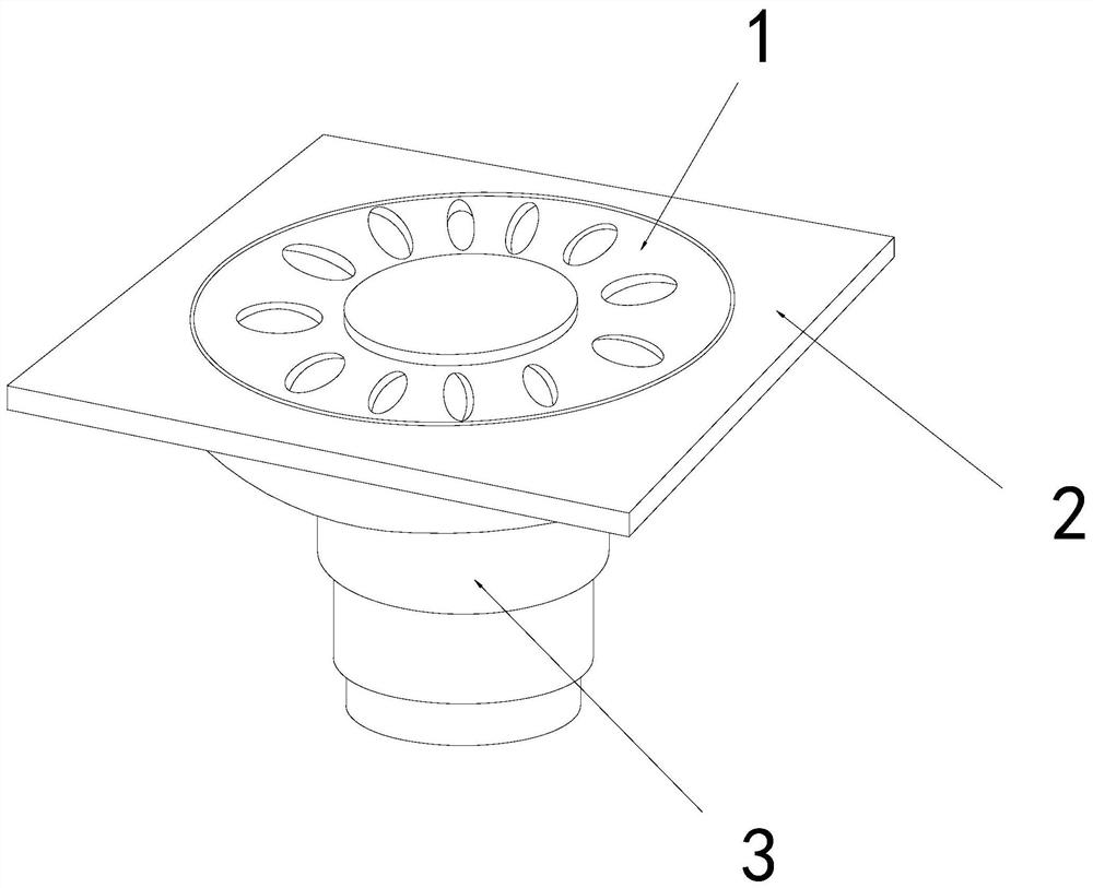
[0026] For example figure 1 -example Figure 5 Shown:

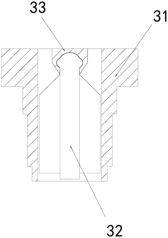
[0027] The present invention provides a drainage device with anti-blocking function, its structure includes a fixed plate 1, a barrier cover 2, and a lower drain pipe 3, the fixed plate 1 is embedded in the inner position of the barrier cover 2, and the lower drain pipe 3 is installed At the bottom position of the barrier cover 2; the lower pipe 3 includes a pipe body 31, an anti-blocking mechanism 32, and a connecting block 33, and the anti-blocking mechanism 32 is movably engaged with the connecting block 33; 31 is an integrated structure.

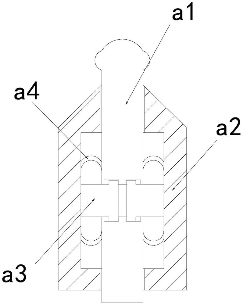
[0028] Wherein, the anti-blocking mechanism 32 includes a central solid rod a1, an outer expansion plate a2, an engaging plate a3, and an elastic piece a4. The fixed rod a1 is movable and engaged, and the elastic sheet a4 is installed between the inner side of the outer expansion plate a2 and the middle solid rod a1. The sides are symmetrically distributed, and the outward thrus...

Embodiment 2

[0034] For example Figure 6 -example Figure 8 Shown:

[0035] Wherein, the swing blade b1 includes a force plate b11, a water storage mechanism b12, and a bottom plate b13, the force plate b11 and the bottom plate b13 are an integrated structure, and the water storage mechanism b12 and the bottom plate b13 The right side of the force plate b11 is embedded and connected, and the force plate b11 has an internal and external transparent structure, and the external waste water can be introduced between the force plate b11 and the bottom plate b13 through the force plate b11.

[0036] Wherein, the water storage mechanism b12 includes a deformable piece c1, a base plate c2, and an upward extension tube c3, the deformation plate c1 is embedded and fixed at the upper end of the base plate c2, and the middle part of the upper extension tube c3 and the deformation plate c1 is movable Snapping, through the waste water between the deformation piece c1 and the bottom plate c2, the upwa...


PUM


Abstract

The invention discloses drainage equipment with an anti-blocking function, which structurally comprises a fixing plate, a blocking cover and a lower drainage pipe, the fixing plate is embedded into the blocking cover, the lower drainage pipe is mounted at the bottom of the blocking cover, and the anti-blocking mechanism can rotate along a connecting block due to the impact force generated by wastewater entering through the fixing plate on the anti-blocking mechanism, so that the anti-blocking function is realized. The cutting knife can cut hair entering the lower discharge pipe into multiple small-size hair sections, so that the small-size hair can be discharged downwards into a sewer line, part of waste water can be discharged between a stress plate and a bottom plate through holes in thestress plate, and then the waste water can be discharged into the sewer line through impact force generated by the waste water on the stress plate. According to the hair washing device, the stress plate can shrink inwards, so that the deformation piece can shrink and deform downwards, the extrusion plate can quickly extrude moisture in the middle outwards, and the extruded moisture can wash awayhair on the stress plate.

Description

technical field [0001] The invention relates to the field of drainage, in particular to a drainage device with an anti-blocking function. Background technique [0002] The anti-blocking drainage floor drain is mainly used to discharge domestic wastewater. It is usually embedded in the bottom plate, and the bottom is connected to the drain pipe, so that the waste water can be discharged into the drain pipe through the anti-blocking drainage floor drain, and the anti-blocking drainage The blocking cover on the floor drain can block the large-volume objects in the wastewater, thereby preventing the drainpipe from being blocked by the large-volume objects. Based on the above description, the inventor found that the existing drainage equipment with anti-blocking There are mainly the following deficiencies, for example: [0003] Because the anti-blocking drainage floor drain blocks the horizontal hair on the upper surface of the barrier cover when blocking the hair, if the shorte...

Claims


Application Information

Patent Timeline
Patent Type & Authority Applications(China)
IPC IPC(8): E03F5/04E03F5/06B02C18/02B02C18/04
CPCB02C18/0084B02C18/02B02C18/04B02C2201/06E03F5/0407E03F5/041E03F5/06
Inventor 李京
Owner 菏泽录苏建筑工程有限公司
Why Eureka
Try Eureka