Eureka AIR delivers breakthrough ideas for toughest innovation challenges, trusted by R&D personnel around the world.

Box transformer substation lock

A box change and lock cylinder technology, applied in the field of box change locks, can solve the problems of non-violent damage, loss of padlocks, high power consumption, etc., and achieve the effects of avoiding vibration, structural safety, and low power consumption

Inactive Publication Date: 2021-02-26
徐州克瑞艾特电子科技有限公司
View PDF0 Cites 0 Cited by
  • Summary
  • Abstract
  • Description
  • Claims
  • Application Information

AI Technical Summary

Problems solved by technology

[0002] At present, the box-type transformer cabinet door lock or terminal box lock of the power company adopts a box-type cabinet lock plus a padlock structure or an electronic lock core passive structure. Due to the limited size of the box body, the padlock is generally 40 padlocks, and the lock beam The diameter is 5mm, which is easy to be damaged by violence. At the same time, the material of the lock nose is zinc alloy, which is easy to be damaged; the characteristic of the padlock is that it is movable, and it is often lost during work and cannot be locked. It is easy to be copied and cannot be managed; the power company uses a large amount of locks and keys, and the management workload is heavy and error-prone
Therefore, the current power box-type transformer lock has problems such as not preventing violent damage, not preventing technical opening, not preventing key duplication, key management workload is heavy, error-prone, and has no management traces, etc.
[0003] In the existing market, the electric control part of the smart box change lock is driven by an electromagnet, which consumes a lot of power and may be opened under vibration and knocking.

Method used


Image

  • Box transformer substation lock
  • Box transformer substation lock
  • Box transformer substation lock

Examples


Embodiment Construction

[0030] The following will clearly and completely describe the technical solutions in the embodiments of the present invention with reference to the accompanying drawings in the embodiments of the present invention. Obviously, the described embodiments are only some, not all, embodiments of the present invention. Based on the embodiments of the present invention, all other embodiments obtained by persons of ordinary skill in the art without making creative efforts belong to the protection scope of the present invention.

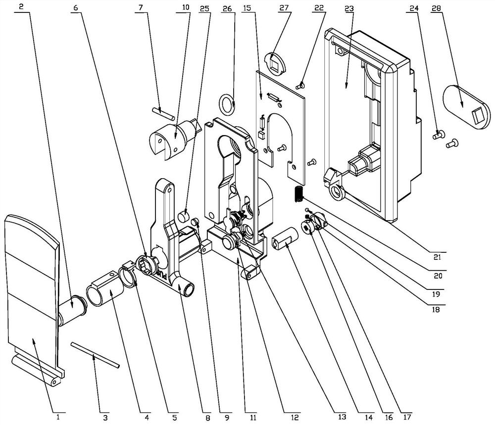
[0031] Such as figure 1 As shown, it is a structural diagram of a box-type lock provided by an embodiment of the present invention, including: a lock main body 23;

[0032] The lock cylinder assembly is arranged inside the lock main body 23, and it includes a hanger;

[0033] The electric control drive assembly is arranged in the internal installation groove of the lock main body 23, and it also includes a motor 14, a deadbolt 21 and a PCB board 15, the motor...


PUM


Abstract

The invention is applicable to the technical field of locks, and provides a box transformer substation lock. The lock comprises a lock main body, a lock cylinder assembly, an electric control drivingassembly, a handle assembly and a control system; the lock cylinder assembly is arranged in the lock main body and comprises a hanging opening; the electric control driving assembly is arranged in a mounting groove in the lock main body and further comprises a motor, a spring bolt and a PCB, the motor is used for the spring bolt to move in a telescopic mode, and the PCB is fixedly mounted on the lock main body; the handle assembly is rotatably arranged on the lock main body and comprises a handle, a rotating shaft and a magnet, the magnet is fixedly installed on the handle, the handle is rotatably installed on the rotating shaft, and the rotating shaft is rotatably installed on the lock main body; the lock cylinder assembly is fixedly installed on the handle assembly, and the PCB is provided with a counting circuit matched with the magnet for counting; and the control system is used for controlling the electric control driving assembly. The motor is adopted for driving the spring bolt,power consumption is low, the structure is safer, and vibration and knocking unlocking can be effectively avoided; and an opening and closing recording function is adopted, so that the opening and closing accuracy of the lock can be confirmed.

Description

technical field [0001] The invention relates to the technical field of locks, in particular to a box change lock. Background technique [0002] At present, the box-type transformer cabinet door lock or terminal box lock of the power company adopts a box-type cabinet lock plus a padlock structure or an electronic lock core passive structure. Due to the limited size of the box body, the padlock is generally 40 padlocks, and the lock beam The diameter is 5mm, which is easy to be damaged by violence. At the same time, the material of the lock nose is zinc alloy, which is easy to be damaged; the characteristic of the padlock is that it is movable, and it is often lost during work and cannot be locked. It is easy to be copied and cannot be managed; the power company uses a large amount of locks and keys, and the management workload is heavy and error-prone. Therefore, the current power box-type transformer lock has problems such as not preventing violent damage, not preventing te...

Claims


Application Information

Patent Timeline
Patent Type & Authority Applications(China)
IPC IPC(8): E05B47/00E05B65/52E05B17/20E05B15/00
CPCE05B15/00E05B17/2084E05B47/0012E05B65/52
Inventor 周强王生
Owner 徐州克瑞艾特电子科技有限公司
Why Eureka
Eureka Blog
Learn More