Compressor refrigerant oil backflow device and air conditioner

A reflux device and refrigeration oil technology, which is applied in the field of compressors, can solve the problems of poor oil separator effect, difficult recovery, oil level protection shutdown, etc., and achieve the effect of weight reduction

Active Publication Date: 2021-02-26
ZHUHAI GREE REFRIGERATION TECH CENT OF ENERGY SAVING & ENVIRONMENTAL PROTECTION
View PDF6 Cites 0 Cited by
  • Summary
  • Abstract
  • Description
  • Claims
  • Application Information

AI Technical Summary

Problems solved by technology

[0002] At present, after the refrigerating oil in the air conditioning system passes through the oil separator, some of the refrigerating oil will be brought into the refrigerating system together with the gaseous refrigerant. The gaseous refrigerant flows out of the compressor, which is difficult to recover. Effective oil return measures must be taken to replenish the refrigeration oil of the compressor in time. Otherwise, if the oil level in the compressor is too low after running for a long time, oil will appear. Bit protection shut down, affecting the normal use of the air conditioning unit
After turning on the machine again, it is still necessary to add additional refrigerant oil. Such a cycle will lead to an excessively high refrigerant oil content in the evaporator of the air-conditioning system, seriously affecting the heat exchange of the evaporator and affecting the efficiency of the unit. The existing oil return system oil separator is less effective. Poor, resulting in too much oil content in the fluorine system, unreasonable design of the oil return system, the refrigeration oil in the fluorine system cannot be returned to the compressor in time, with the accumulation of running time, the compressor will be short of oil, resulting in an oil level alarm and cannot be started normally

Method used


Image

  • Compressor refrigerant oil backflow device and air conditioner
  • Compressor refrigerant oil backflow device and air conditioner
  • Compressor refrigerant oil backflow device and air conditioner

Examples


Embodiment 1

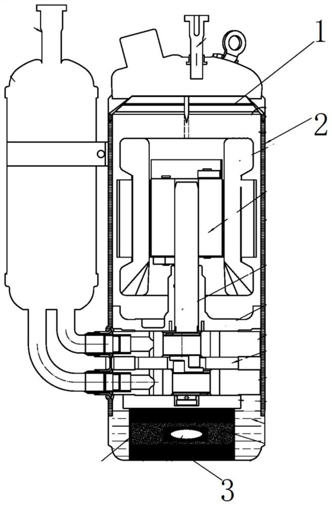
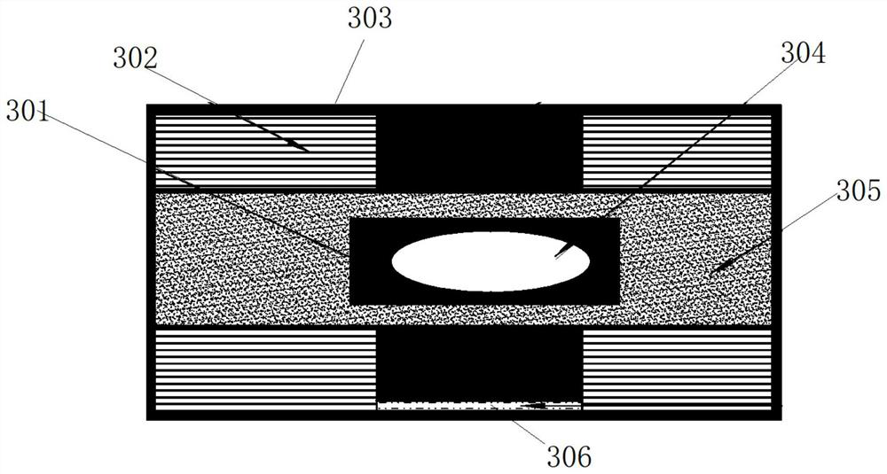
[0027] Such as figure 1 As shown, a compressor refrigerating oil return device includes a casing, the casing is provided with a stator and a pump body, the bottom of the casing is provided with refrigerating oil, and the inside of the casing is provided with a suction plate 1 and a magnetic Seat 3, the suction plate 1 is located above the stator, the magnetic base 3 is located in the refrigerated oil and connected to the bottom of the casing, the upper end of the magnetic base 3 is connected to the pump body, and the magnetic base 3 is electrically connected to the suction plate 1 Connection, the inside of the casing is vertically provided with an oil return pipe 2, the oil return pipe 2 is made of antimagnetic material, the upper end of the oil return pipe 2 is connected with the suction plate 1, and the lower end of the oil return pipe 2 is located in the refrigerated oil.

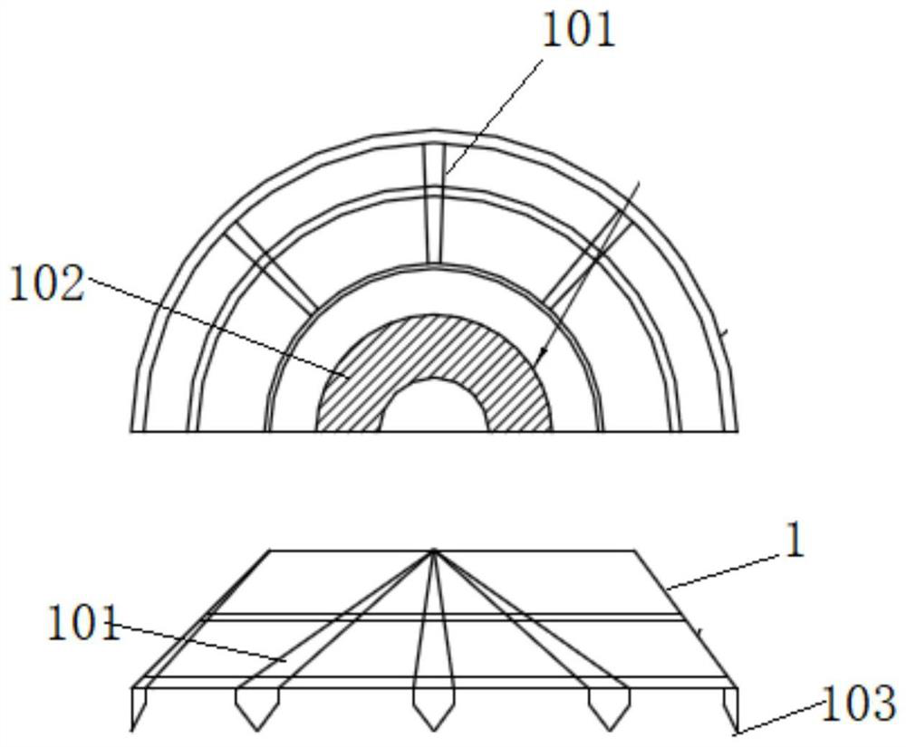
[0028] Such as figure 2 As shown, the suction plate 1 is a cylindrical structure, and the diameter ...

Embodiment 2

[0036] Such as figure 1 As shown, a compressor refrigerating oil return device includes a casing, the casing is provided with a stator and a pump body, the bottom of the casing is provided with refrigerating oil, and the inside of the casing is provided with a suction plate 1 and a magnetic Seat 3, the suction plate 1 is located above the stator, the magnetic base 3 is located in the refrigerated oil and connected to the bottom of the casing, the upper end of the magnetic base 3 is connected to the pump body, and the magnetic base 3 is electrically connected to the suction plate 1 Connection, the inside of the casing is vertically provided with an oil return pipe 2, the oil return pipe 2 is made of antimagnetic material, the upper end of the oil return pipe 2 is connected with the suction plate 1, and the lower end of the oil return pipe 2 is located in the refrigerated oil.

[0037] Such as figure 2 As shown, the suction plate 1 is a cylindrical structure, and the diameter ...

Embodiment 3

[0043]Such as Figure 1-4 As shown, an air conditioner includes a compressor refrigeration oil return device, including a casing, a stator and a pump body are arranged inside the casing, refrigeration oil is arranged at the bottom of the casing, and a suction plate is arranged inside the casing 1 and magnetic base 3, the suction plate 1 is located above the stator, the magnetic base 3 is located in the refrigeration oil and connected to the bottom of the casing, the upper end of the magnetic base 3 is connected to the pump body, and the magnetic base 3 is connected to the suction The plate 1 is electrically connected, and the inside of the casing is vertically provided with an oil return pipe 2, which is made of antimagnetic material. The upper end of the oil return pipe 2 is connected with the suction plate 1, and the lower end of the oil return pipe 2 is located in the refrigeration oil.

[0044] The suction plate 1 is a cylindrical structure, and the diameter of the suction...


PUM


Abstract

The invention discloses a compressor refrigerant oil backflow device and an air conditioner. The device comprises a machine shell, a stator and a pump body are arranged in the machine shell, refrigerant oil is arranged at the bottom of the machine shell, a suction plate and a magnetic base are arranged in the machine shell, the suction plate is located above the stator, the magnetic base is located in the refrigerant oil and connected with the bottom of the machine shell, the upper end of the magnetic base is connected with the pump body, the magnetic base is electrically connected with the suction plate, an oil return pipe is vertically arranged in the machine shell, the upper end of the oil return pipe is connected with the suction plate, and the lower end of the oil return pipe is located in the refrigerant oil. Quantitative magnetic liquid is injected into a compressor, the density of the magnetic liquid is larger than that of the refrigerant oil, so that refrigerant oil particlesare attached to magnetic particles; and the magnetic fluid is adsorbed before a gaseous refrigerant flows out of a pipe orifice, so that the oil attached to the magnetic fluid returns to an oil pool at the bottom of the compressor along with a specific magnetic circuit to form a closed loop, and then the oil quantity in the compressor is kept constant.

Description

technical field [0001] The invention relates to the technical field of compressors, in particular to a compressor refrigeration oil return device and an air conditioner. Background technique [0002] At present, after the refrigerated oil in the air conditioning system passes through the oil separator, part of the refrigerated oil will be brought into the refrigeration system together with the gaseous refrigerant. Since the refrigerated oil is trapped in the gaseous refrigerant and flows out of the compressor, it is difficult to recover, and effective measures must be taken. Oil return measures can make the refrigeration oil of the compressor replenished in time. Otherwise, if the oil level in the compressor is too low after running for a long time, oil level protection shutdown will occur, which will affect the normal use of the air conditioning unit. After turning on the machine again, it is still necessary to add additional refrigerant oil. Such a cycle will lead to an ex...

Claims


Application Information

Patent Timeline
Patent Type & Authority Applications(China)
IPC IPC(8): F04C29/02F16F15/03
CPCF04C29/026F04C29/028F16F15/035
Inventor 郭晓东张文科
Owner ZHUHAI GREE REFRIGERATION TECH CENT OF ENERGY SAVING & ENVIRONMENTAL PROTECTION
Why Eureka
Try Eureka