
Method and system for realizing visualization of operation working points of axial flow fan

An axial flow fan, working point technology, applied in wind power generation, mechanical equipment, machines/engines, etc., can solve the fan surge, cannot realize the real-time working point information of the fan, has a large safety margin, and has a large operating efficiency, which is not conducive to the fan and its belongings. System stability and economic operation, etc.

Active Publication Date: 2021-02-26
国能开远发电有限公司
View PDF5 Cites 0 Cited by
  • Summary
  • Abstract
  • Description
  • Claims
  • Application Information

AI Technical Summary

Problems solved by technology

[0002] In the operation of large axial flow fans, the position of the working point is very important. Once the working point is in the unstable area, the fan is prone to abnormal conditions such as surge and stall, which seriously threaten the safety of the equipment; when the working point is in the stable area, There may also be large differences in the efficiency of different operating points
At present, the operating personnel can only make a preliminary judgment on the operating status of the axial flow fan through indicators such as current, vibration, and system wind pressure. Especially in the process of changing the load of the fan, it is only possible to wait for the actual problem of the fan to see if there is any abnormality in the fan. In order to know, it is impossible to know the real-time operating point information of the fan during the adjustment process (such as how large the safety margin is and how high the operating efficiency is)
This is very detrimental to the stable and economical operation of the fan and its associated system

Method used


Image

  • Method and system for realizing visualization of operation working points of axial flow fan
  • Method and system for realizing visualization of operation working points of axial flow fan
  • Method and system for realizing visualization of operation working points of axial flow fan

Examples


Embodiment 1

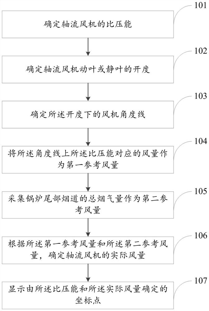
[0050] see figure 1 , this embodiment provides a method for realizing the visualization of the operating point of the axial flow fan, the method includes the following steps:

[0051] Step 101: Determine the specific pressure energy of the axial flow fan.

[0052] In practical applications, the inlet wind pressure, outlet wind pressure and flue gas temperature of the axial flow fan are collected online in real time, and are calculated according to the formula Calculate the specific pressure energy of the axial flow fan in real time, where, ΔP=P o -P i , ΔP is the differential pressure of the axial flow fan, P o is the outlet air pressure of the axial flow fan, P i is the inlet wind pressure of the axial flow fan, ρ is the density of flue gas, ρ 0 The flue gas apparent density is designed for the boiler, and t is the inlet flue gas temperature of the axial flow fan.

[0053] Step 102: Determine the opening m of the rotor blades or stationary blades of the axial flow fa...

Embodiment 2

[0071] see Figure 4 , this embodiment provides a system for realizing the visualization of the operating point of the axial flow fan, the system includes:

[0072] The specific pressure energy determination module 401 is used to determine the specific pressure energy of the axial flow fan;

[0073] The blade opening degree determination module 402 is used to determine the opening degree of the rotor blade or stator blade of the axial flow fan;

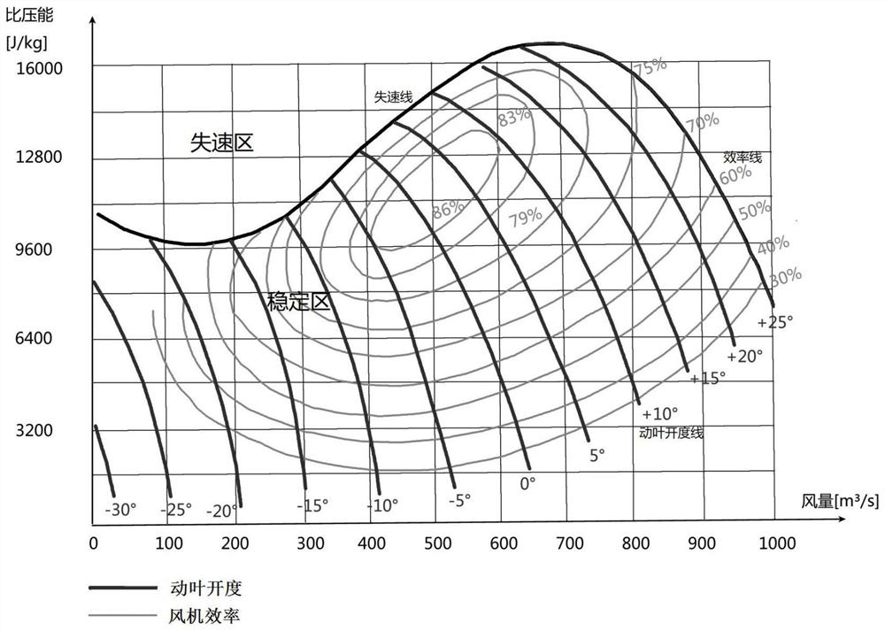
[0074] An angle line determining module 403, configured to determine the fan angle line under the opening degree;

[0075] The first reference air volume determination module 404 is configured to use the air volume corresponding to the specific pressure energy on the angle line as the first reference air volume;

[0076] The second reference air volume determination module 405 is used to collect the total flue gas volume of the tail flue of the boiler as the second reference air volume;

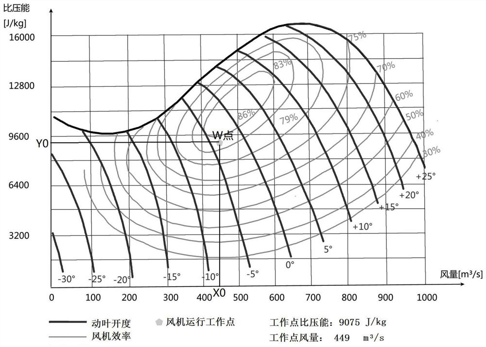
[0077] An actual air volume determination m...


PUM


Abstract

The invention discloses a method and a system for realizing visualization of operation working points of an axial flow fan. The method comprises the steps that the specific pressure energy of the axial flow fan is determined; the opening degree of a moving blade or a static blade of the axial flow fan is determined; a fan angle line under the opening degree is determined; the air volume corresponding to the specific pressure energy on the angle line is used as a first reference air volume; the total smoke amount of a tail flue of a boiler is collected to serve as a second reference air volume;the actual air volume of the axial flow fan is determined according to the first reference air volume and the second reference air volume; and a coordinate point determined by the specific pressure energy and the actual air volume is displayed. According to the method, the working points of the axial flow fan are marked in a fan flow characteristic curve graph, thus, an operator can accurately and timely master the working state of the fan, and effective guidance is provided for the operator to adjust the operating state of the fan.

Description

technical field [0001] The invention relates to the fields of energy and chemical industry, in particular to a method and system for realizing the visualization of the operating point of an axial flow fan. Background technique [0002] In the operation of large axial flow fans, the position of the working point is very important. Once the working point is in the unstable area, the fan is prone to abnormal conditions such as surge and stall, which seriously threaten the safety of the equipment; when the working point is in the stable area, There may also be large differences in the efficiency of different operating points. At present, the operating personnel can only make a preliminary judgment on the operating status of the axial flow fan through indicators such as current, vibration, and system wind pressure. Especially in the process of changing the load of the fan, it is only possible to wait for the actual problem of the fan to see if there is any abnormality in the fan....

Claims


Application Information

Patent Timeline
Patent Type & Authority Applications(China)
IPC IPC(8): F04D27/00
CPCF04D27/001Y02E10/72
Inventor 魏兴文张子明凌国峰熊方张勇前
Owner 国能开远发电有限公司
Features
  • Generate Ideas
  • Intellectual Property
  • Life Sciences
  • Materials
  • Tech Scout
  • Unparalleled Data Quality
  • Higher Quality Content
  • 60% Fewer Hallucinations
Learn More