Splicing type fixing device for automatic instrument

A fixed device and splicing technology, which is applied in the direction of non-rotational vibration suppression, supporting machines, mechanical equipment, etc., can solve the problems of inconvenient dismantling of instruments, lack of instruments, time-consuming and labor-intensive efficiency, etc., to achieve easy dismantling, time-saving and labor-saving efficiency effect

Inactive Publication Date: 2021-02-26
XIAN ZHIYUEDA SOFTWARE CO LTD
View PDF2 Cites 0 Cited by
  • Summary
  • Abstract
  • Description
  • Claims
  • Application Information

AI Technical Summary

Problems solved by technology

[0008] The purpose of the present invention is to solve the problem in the prior art that the instrument does not have the function of preliminary positioning during installation, so that the instrument is easy to

Method used


Image

  • Splicing type fixing device for automatic instrument
  • Splicing type fixing device for automatic instrument
  • Splicing type fixing device for automatic instrument

Examples


Embodiment 1

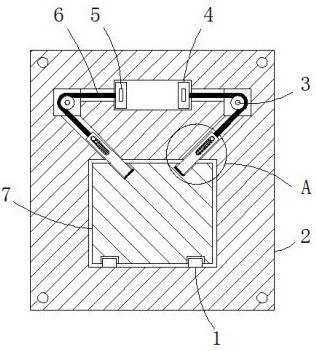
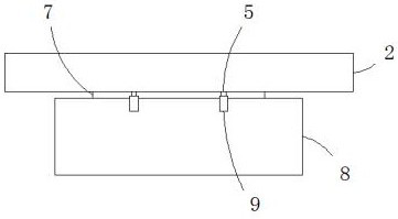
[0025] Example 1 as Figure 1-3 As shown, this spliced ​​fixing device for automatic instruments includes a mounting plate 2 and an instrument body 8 arranged on the front side of the mounting plate. A rectangular hole is opened in the middle of the front side wall of the mounting plate 2, and a fixing block is slidably connected inside the rectangular hole. 7. The front side wall of the fixed block 7 extends to the outside of the rectangular hole and is fixedly connected with the rear side wall of the instrument body 8. The left and right ends of the lower side hole wall of the rectangular hole are symmetrically fixedly connected with the block 1, and the lower end of the fixed block 7 The left and right sides are provided with the first card slots matching with the two clamping blocks 1, the inside of the mounting plate 2 is located on the upper side of the rectangular hole and a first cavity is opened, and the inside of the mounting plate 2 is located in the first cavity Th...

Embodiment 2

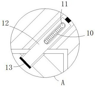
[0026] Embodiment 2 is on the basis of embodiment 1 such as image 3 As shown, its clamping mechanism includes a clamping rod 12, a fixed rod 11 and a spring 10. The rod wall of the clamping rod 12 is slidably connected with the hole wall of the second through hole, and one end of the clamping rod 12 close to the rectangular hole extends to a rectangular In the inside of the hole, the side wall of the fixed block 7 is provided with a second draw-in groove matched with the clamp rod 12, and the front side wall of the clamp rod 12 is provided with a first strip-shaped hole, and the fixed rod 11 is longitudinally arranged in the first strip-shaped hole. and the front and rear ends of the fixed rod 11 are fixedly connected with the hole wall of the second through hole, and the two ends of the two springs 10 are respectively connected with the side rod wall of the fixed rod 11 near the rectangular hole and the first bar-shaped hole. The hole wall is fixedly connected.

Embodiment 3

[0027] Embodiment 3 is such as on the basis of embodiment 1 figure 1 As shown, its pulling mechanism includes a roller 3, a pull cord 6, a slider 4 and a connecting block 5, the roller 3 is rotationally connected with the wall of the second cavity through a rotating shaft, and the slider 4 is connected with the wall of the first cavity. Slidingly connected, one end of the stay cord 6 is fixedly connected to one end of the clamp rod 12 located in the second through hole, and the other end of the stay cord 6 goes around the roller 3 and passes through the first through hole to be fixedly connected to the slider 4. The block 5 is fixedly connected to the front side wall of the slider 4, and the front side wall of the first cavity is vertically provided with a second strip-shaped hole matched with the connecting block 5, and the front side wall of the connecting block 5 passes through the second The strip-shaped hole extends to the outside of the first cavity.


PUM


Abstract

The invention relates to the technical field of instrument equipment, and discloses a splicing type fixing device for an automatic instrument. The splicing type fixing device comprises a mounting plate and an instrument body arranged on the front side of the mounting plate, wherein a rectangular hole is formed in the middle of the front side wall of the mounting plate, a fixing block is slidably connected to the interior of the rectangular hole, the front side wall of the fixing block extends to the outside of the rectangular hole and is fixedly connected with the rear side wall of the instrument body, clamping blocks are symmetrically and fixedly connected to the left end and the right end of the lower side hole wall of the rectangular hole, first clamping grooves matched with the two clamping blocks are respectively formed in the left side and the right side of the lower end of the fixing block, a first cavity is formed in the position, located on the upper side of the rectangular hole, of the interior of the mounting plate, and second cavities are symmetrically formed in the positions, located on the left side and the right side of the first cavity, of the interior of the mounting plate. According to the splicing type fixing device, the instrument can be preliminarily positioned conveniently during installation, so that the instrument is not prone to falling onto the groundto be damaged, the instrument can be conveniently disassembled during maintenance, the time and labor are saved, and the efficiency is high.

Description

technical field [0001] The invention relates to the technical field of instrument equipment, in particular to a spliced ​​fixing device for automatic instruments. Background technique [0002] Instrumentation is an instrument or device used to detect, measure, observe, and calculate various physical quantities, material components, and physical parameters. It is widely used in instruments, meters, electronics, communications, automation, sensors, smart cards, industrial control, and precision machinery. and other industries. [0003] The existing spliced ​​fixing devices for automated instruments do not have the function of preliminary positioning of the instrument during installation, which makes the instrument easy to fall to the ground and cause damage, and it is inconvenient to remove the instrument during maintenance, which is time-consuming, laborious and inefficient. In the patent No. CN207796449U, it relates to a spliced ​​fixing device for automatic instruments, wh...

Claims


Application Information

Patent Timeline
IPC IPC(8): F16M11/04F16F15/08
CPCF16F15/08F16M11/04
Inventor 朱明月
Owner XIAN ZHIYUEDA SOFTWARE CO LTD
Why Eureka
Try Eureka