Method for analyzing visual continuousness between uniform parting curved surfaces based on human eye visual limit

A technology of human vision and uniform division, which is applied in image analysis, image data processing, instruments, etc., can solve the problem of not considering the continuity of the curved surfaces on both sides of the slit, and achieve the effect of improving the sense of integrity and the sense of refinement.

Pending Publication Date: 2021-02-26
CHONGQING CHANGAN AUTOMOBILE CO LTD
View PDF0 Cites 0 Cited by
  • Summary
  • Abstract
  • Description
  • Claims
  • Application Information

AI Technical Summary

Problems solved by technology

The continuity of the curved surfaces on both sides of the split is not considered from the perspective of the customer
However, the unavoidable seams on the appearance of the product contradict the requirements for a seamless and exquisite appearance

Method used


Image

  • Method for analyzing visual continuousness between uniform parting curved surfaces based on human eye visual limit
  • Method for analyzing visual continuousness between uniform parting curved surfaces based on human eye visual limit
  • Method for analyzing visual continuousness between uniform parting curved surfaces based on human eye visual limit

Examples


Embodiment example 1

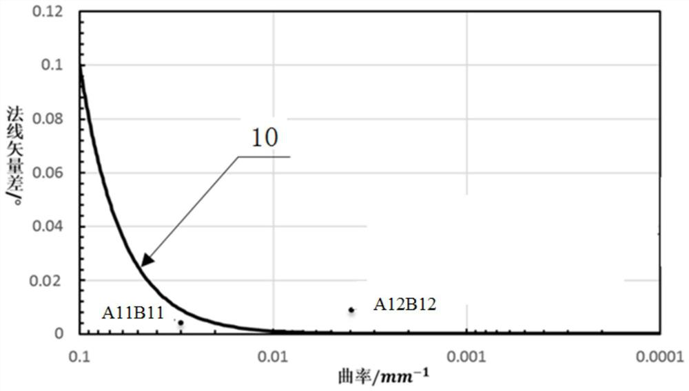
[0048] Implementation case 1: Analysis of the sense of continuity for the 0-point gap between surfaces:

[0049] Step 1: Take points A11 and A12 on the boundary line of a curved surface in the area to be analyzed, and correspondingly take points B11 and B12 on the boundary line of the matching surface, where the distances between A11 and B11, A12 and B12 are all 0. Obtain the curvature of A11 and A12 positions, which are 0.03021mm respectively -1 , 0.004002mm -1 ; Obtain the normal vector differences between A11 and B11, A12 and B12, which are 0.00528° and 0.008925° respectively. Recorded as coordinates: A11B11 (0.03021, 0.00528), A12B12 (0.004002, 0.008925).

[0050] Step 2: Since the gap between surfaces is 0, select the threshold line equation:

[0051] θ=10f 2 +0.001f+0.0001;

[0052] Constructed face-to-face matching continuity analysis model, see image 3 .

[0053] Step 3: Bring the coordinates of the two matching positions A11B11 (0.03021, 0.00528) and A12B12 (0.0...

Embodiment example 2

[0056] Implementation case 2: Analysis of the sense of continuity with a gap of 3 mm between surfaces:

[0057] Step 1: Take points A21 and A22 on the boundary line of a curved surface in the area to be analyzed, and correspondingly take points B21 and B22 on the boundary line of the matching surface, where the distances between A21 and B21, A22 and B22 are all 3mm. Obtain The curvatures at A21 and A22 are 0.01157mm respectively -1 、0.02722mm -1 ; Obtain the normal vector differences between A21 and B21, A22 and B22, which are 4.185° and 47.887° respectively. Recorded as coordinates: A21B21 (0.01157, 4.185°), A22B22 (0.02722, 47.887).

[0058] Step 2: Since the gap between surfaces is 3mm, select the threshold line equation:

[0059] θ=10000f 2 +600f+0.4;

[0060] Build the model.

[0061] The third step: Bring the coordinates of the two matching positions A21B21 (0.01157, 4.185°) and A22B22 (0.02722, 47.887) into the model selected in the second step, and draw the map. ...

Embodiment example 3

[0064] Implementation case 3: Analysis of the sense of continuity for a gap of 6 mm between surfaces:

[0065] Step 1: Take points A31, A32, and A33 on the boundary line of a curved surface in the area to be analyzed, and correspondingly take points B31, B32, and B33 on the boundary line of the matching surface, where A31 and B31, A32 and B32, A33 and The distance of B33 is 6mm. Obtain the curvature of A31, A32, and A33 positions, which are 0.007142mm-1, 0.004178mm-1, and 0.01525mm-1 respectively; obtain the normal vectors of A31 and B31, A32 and B32, A33 and B33 The differences are 6.852°, 40.923°, and 23.541°, respectively. Recorded as coordinates: A31B31 (0.007142, 6.852), A32B32 (0.004178, 40.923), A33B33 (0.01525, 23.541).

[0066] Step 2: Since the gap between surfaces is 6mm, select the threshold line equation:

[0067] θ=40000f 2 +1200f+1;

[0068] Build the model.

[0069] The third step: Bring the coordinates of the three matching positions A31B31 (0.007142, 6.8...


PUM


Abstract

The invention discloses a method for analyzing visual continuousness between uniform parting curved surfaces based on human eye visual limit. The method comprises the following steps: acquiring information of gaps, curvatures and normal vector differences of corresponding points on curved surface boundary lines on two sides of a parting needing to be analyzed; selecting a corresponding face-to-face matching continuity analysis model according to the gap of the parting; inputting the curvature and the normal vector difference of the curved surface boundaries on the two sides of the parting intothe selected surface-to-surface matching continuity analysis model in a coordinate form; when the input coordinate is located above the threshold line, considering that the position vision between the curved surfaces corresponding to the coordinate is discontinuous; when the input coordinates are located below the threshold line, considering that the positions between the curved surfaces corresponding to the coordinates are visually continuous; when the input coordinates are located on the threshold line, considering that the positions between the curved surfaces corresponding to the coordinates are visually continuous, but the risk of visual discontinuity exists; and 5, outputting an analysis result. The invention can quantitatively evaluate the visual continuity of the matching area between the curved surfaces.

Description

technical field [0001] The invention belongs to the technical field of curved surface quality analysis, and in particular relates to a method for analyzing the sense of visual continuity between evenly divided curved surfaces based on the visual limit of human eyes. Background technique [0002] At present, the product design department mostly has its own quality standards for the A-level and B-level surfaces that can be perceived by customers. For example, G0 continuity (that is, point continuity) is not greater than 0.05mm, G1 continuity (that is, tangent continuity) is not greater than 0.15°, G2 continuity (curvature continuity) is not greater than 0.5, and some special surfaces also require G3 continuity (continuous curvature change rate), etc. . [0003] At present, each product design department mainly determines the seam line between the curved surface and the curved surface through two aspects of product structure and process feasibility. The continuity of the curv...

Claims


Application Information

Patent Timeline
Patent Type & Authority Applications(China)
IPC IPC(8): G06T7/00
CPCG06T7/0004G06T2207/10012G06T2207/30168
Inventor 范坤王锐彭静陈浩铭龚成云张劲松
Owner CHONGQING CHANGAN AUTOMOBILE CO LTD
Why Eureka
Try Eureka