Supercharge Your Innovation With Domain-Expert AI Agents!

Target position recognition method and device based on FPGA and electronic equipment

A recognition method and target position technology, which is applied in image analysis, image enhancement, instruments, etc., can solve the problems of target paper image deformation and low reliability of target position recognition results, and achieve the effect of improving accuracy

Pending Publication Date: 2021-02-26
SHENZHEN UNIV
View PDF0 Cites 0 Cited by
  • Summary
  • Abstract
  • Description
  • Claims
  • Application Information

AI Technical Summary

Problems solved by technology

[0004] However, due to the influence of the application environment, the camera that collects the image is not necessarily facing the target paper directly, resulting in a certain deformation of the collected target paper image, which in turn leads to low reliability of the target recognition results obtained.

Method used


Image

  • Target position recognition method and device based on FPGA and electronic equipment
  • Target position recognition method and device based on FPGA and electronic equipment
  • Target position recognition method and device based on FPGA and electronic equipment

Examples


Embodiment Construction

[0074] In order to make the purposes, technical solutions and advantages of the embodiments of the present application clearer, the technical solutions in the embodiments of the present application will be clearly and completely described below in conjunction with the drawings in the embodiments of the present application. Obviously, the described embodiments It is a part of the embodiments of this application, not all of them. Based on the embodiments in this application, all other embodiments obtained by persons of ordinary skill in the art without creative efforts fall within the protection scope of this application.

[0075] In addition, the terms "first", "second", etc. are used for descriptive purposes only, and should not be interpreted as indicating or implying relative importance or implicitly specifying the quantity of the indicated technical features. In the descriptions of the following embodiments, "plurality" means two or more, unless otherwise specifically defin...


PUM


Abstract

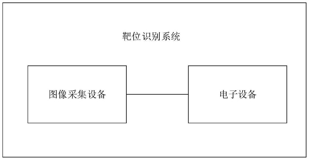
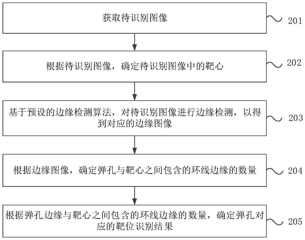
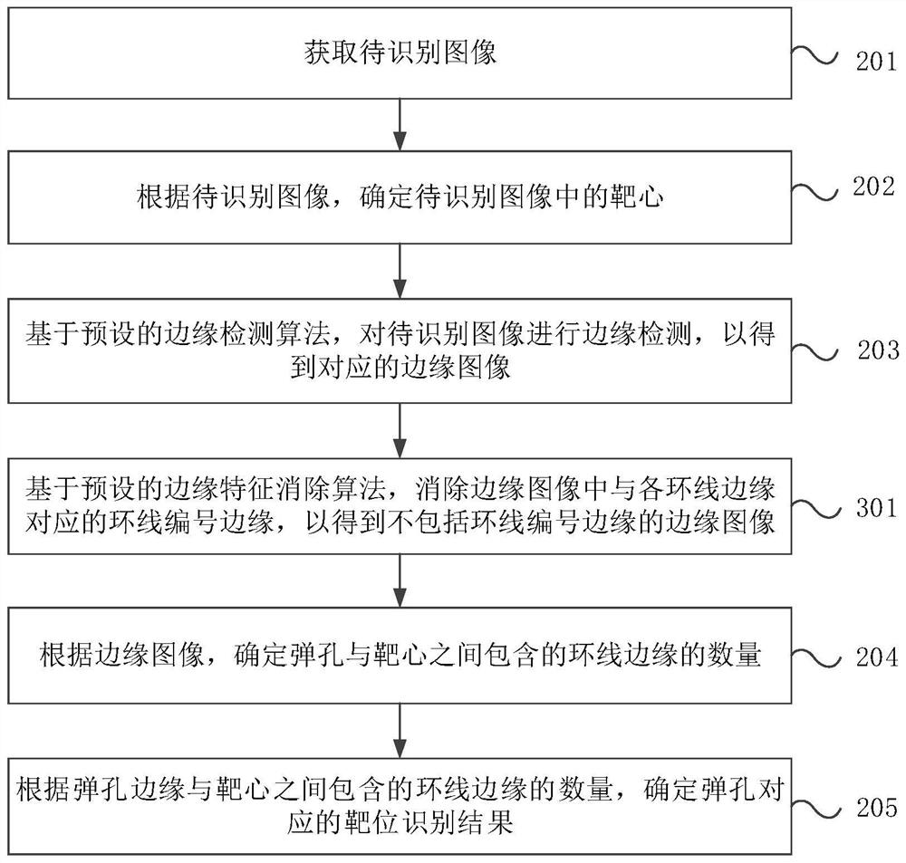
The invention provides a target position recognition method and device based on an FPGA and electronic equipment. The method comprises the steps: acquiring a to-be-recognized image, wherein the to-be-recognized image at least comprises a bullet hole and a plurality of loop lines; determining a target center in the to-be-recognized image according to the to-be-recognized image; based on a preset edge detection algorithm, carrying out edge detection on the to-be-recognized image to obtain a corresponding edge image, wherein the edge image at least comprises a bullet hole edge and each loop lineedge; according to the edge image, determining the number of loop line edges contained between the bullet hole and the bull's-eye; and determining a target position identification result correspondingto the bullet hole according to the number of loop edges included between the bullet hole edge and the bull's-eye. According to the target position identification method based on the FPGA provided bythe scheme, the target position corresponding to the bullet hole is determined by detecting the number of the loop lines spaced between the bullet hole and the bull's-eye, so that the accuracy of thetarget position identification result is improved.

Description

technical field [0001] The present application relates to the technical field of artificial intelligence, in particular to an FPGA-based target recognition method, device and electronic equipment. Background technique [0002] With the development of science and technology, artificial intelligence technology has been applied to all walks of life, and has also been widely used in the field of shooting training, such as automatic target reporting. [0003] The automatic target reporting technology in the prior art usually performs image processing on the collected images to identify the bullet hole and the bull's-eye, and then determines the target position corresponding to the current bullet hole according to the distance between the bullet hole and the bull's-eye, that is, to obtain Target recognition results, and finally report the target recognition results. [0004] However, due to the influence of the application environment, the camera that collects the image is not ne...

Claims


Application Information

Patent Timeline
IPC IPC(8): G06T7/13G06T7/136G06T7/155G06T7/66G06T5/00
CPCG06T7/13G06T7/136G06T7/155G06T7/66G06T2207/20028G06T2207/20036G06T5/70
Inventor 卿易李昆华朱明程
Owner SHENZHEN UNIV
Features
  • R&D
  • Intellectual Property
  • Life Sciences
  • Materials
  • Tech Scout
  • Unparalleled Data Quality
  • Higher Quality Content
  • 60% Fewer Hallucinations
Learn More