Self-aligning wireless charging device and working method thereof, and wireless charging system

A wireless charging and working method technology, applied in circuit devices, electrical components, etc., can solve the problems of limited wireless charging equipment compatibility, incompatibility with wireless charging systems, incompatibility with other equipment charging, etc., so as to improve charging efficiency and reduce electromagnetic Interference, simple structure effect

Pending Publication Date: 2021-02-26
ZHUHAI ISMARTWARE TECH CO LTD
View PDF0 Cites 2 Cited by
  • Summary
  • Abstract
  • Description
  • Claims
  • Application Information

AI Technical Summary

Problems solved by technology

The following four self-alignment solutions are currently known: 1. Using magnet alignment solutions, for example, the magnetic charger on the Apple Watch, the MagSafe charger and Qi’s early A1 coil solution, which has alignment accuracy High advantages, but it will affect other electronic devices, and it is not compatible with the current Qi wireless charging system; 2. Using the scheme of multiple transmitting coils, arrange multiple transmitting coils in a certain plane, and select the transmitting coil closest to the receiving coil For energy transmission, it has the advantage of free placement, but requires multiple transmitting coils, which is costly, and the closest coil selected still has the possibility of large alignment deviation; 3. Use the moving transmitting coil to achieve alignment, Generally, a coil moving structure with at

Method used


Image

  • Self-aligning wireless charging device and working method thereof, and wireless charging system
  • Self-aligning wireless charging device and working method thereof, and wireless charging system
  • Self-aligning wireless charging device and working method thereof, and wireless charging system

Examples


Embodiment Construction

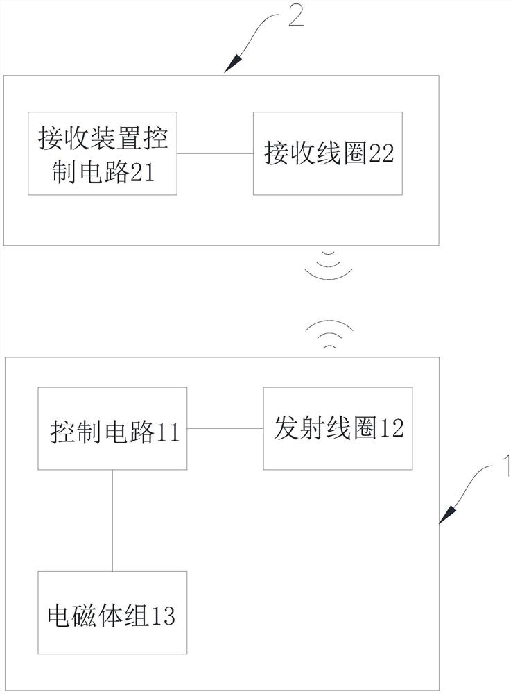
[0037] Such as figure 1 As shown, in this embodiment, the wireless charging system includes a self-aligning wireless charging device 1 and a receiving device 2 , and the self-aligning wireless charging device 1 and the receiving device 2 cooperate to complete the charging operation.

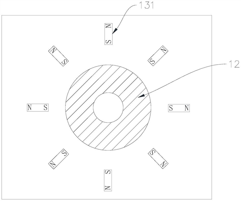
[0038] The self-aligning wireless charging device 1 includes a control circuit 11 , a transmitting coil 12 and an electromagnet group 13 , and both the transmitting coil 12 and the electromagnet group 13 are electrically connected to the control circuit 11 . see figure 2 , the electromagnet group 13 includes a plurality of electromagnets 131 , all the electromagnets 131 are electrically connected to the control circuit 11 , and all the electromagnets 131 are evenly distributed on the outer circumference of the transmitting coil 12 . The control circuit 11 sends or receives signals to the receiving device 2 through the transmitting coil 12 , and completes the charging operation through the trans...


PUM


Abstract

The invention provides a self-aligning wireless charging device and a working method thereof, and a wireless charging system. The device comprises a control circuit, a transmitting coil and a plurality of electromagnets; the transmitting coil and all the electromagnets are electrically connected with the control circuit, and all the electromagnets are uniformly distributed at the periphery of thetransmitting coil. The method comprises the steps: judging whether an object enters or not, and if the object enters, sending a handshake communication signal through the transmitting coil; if handshake communication succeeds, supplying power to the electromagnets for magnetic attraction operation; acquiring the intensity of a first signal received by the transmitting coil during the first communication and the intensity of a second signal received by the transmitting coil after the magnetic attraction operation is completed; and if the second signal intensity is greater than or equal to the first signal intensity, starting charging operation. The system applies the device. The applied self-alignment wireless charging device is simple in structure, interference to other electronic equipment can be reduced, and the alignment degree is improved.

Description

technical field [0001] The present invention relates to the technical field of wireless charging, in particular to a self-aligned wireless charging device, a working method of the self-aligning wireless charging device, and a wireless charging system using the self-aligning wireless charging device. Background technique [0002] In order to improve the safety of the wireless charging system and the effect of power transmission, the current common practice is to set up a self-aligning structure so that the transmitting coil and the receiving coil can be accurately docked. The following four self-alignment solutions are currently known: 1. Using magnet alignment solutions, for example, the magnetic charger on the Apple Watch, the MagSafe charger and Qi’s early A1 coil solution, which has alignment accuracy High advantages, but it will affect other electronic devices, and it is not compatible with the current Qi wireless charging system; 2. Using the scheme of multiple transmit...

Claims


Application Information

Patent Timeline
IPC IPC(8): H02J50/10H02J50/90
CPCH02J50/10H02J50/90
Inventor 黄穗彪邓琴
Owner ZHUHAI ISMARTWARE TECH CO LTD
Why Eureka
Try Eureka