Selective axis serrated rod low profile spinal fixation system
What is Al technical title?
Al technical title is built by PatSnap Al team. It summarizes the technical point description of the patent document.
a spinal fixation system and serrated rod technology, applied in the field of spinal disorders, can solve the problems of system being very complicated, system being expensive to manufacture and/or difficult to implant, and the system being more likely to come out of alignment when the patient is present, and achieves the effect of simple alignmen
Inactive Publication Date: 2006-03-23
MEDICAL DEVICE ADVISORY DEV GROUP
View PDF99 Cites 181 Cited by
Summary
Abstract
Description
Claims
Application Information
AI Technical Summary
This helps you quickly interpret patents by identifying the three key elements:
Problems solved by technology
Method used
Benefits of technology
[0024] In accordance with another aspect of the present invention, a method is provided for simple alignment or otherwise stabilizing vertebrae relative to one another using a plurality of swing bolt anchor screw assemblies, such as those described above. A threaded portion of a first swing bolt anchor screw is screwed into a first vertebra until a first pivot axis of the first swing bolt anchor screw is generally parallel to the spinal axis. A threaded portion of a second swing bolt anchor screw is screwed into a second vertebra adjacent the first vertebra until a second pivot axis of the second swing bolt anchor screw is substantially transverse to the first pivot axis. If desired, a third anchor screw (or more) may be screwed into other vertebra adjacent to the first vertebra.
Problems solved by technology
However, because the system of the '166 patent is polyaxial, i.e., may pivot about multiple axes, there is greater risk of the system coming out of alignment when the patient resumes normal physical activity.
This system is also very complicated, involving six parts, including three set screws, that are mounted on each swing bolt anchor screw.
Thus, because of its complexity and many intricate parts, this system may be expensive to manufacture and / or difficult to implant.
Method used
Image
Click on the blue label to locate the original text in one second.
Reading with bidirectional positioning of images and text.
Examples
Embodiment Construction
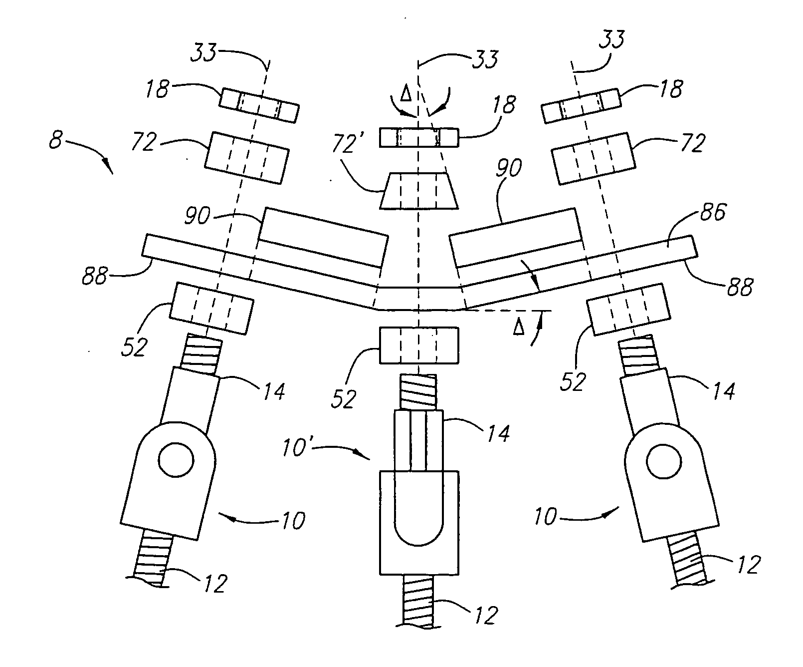
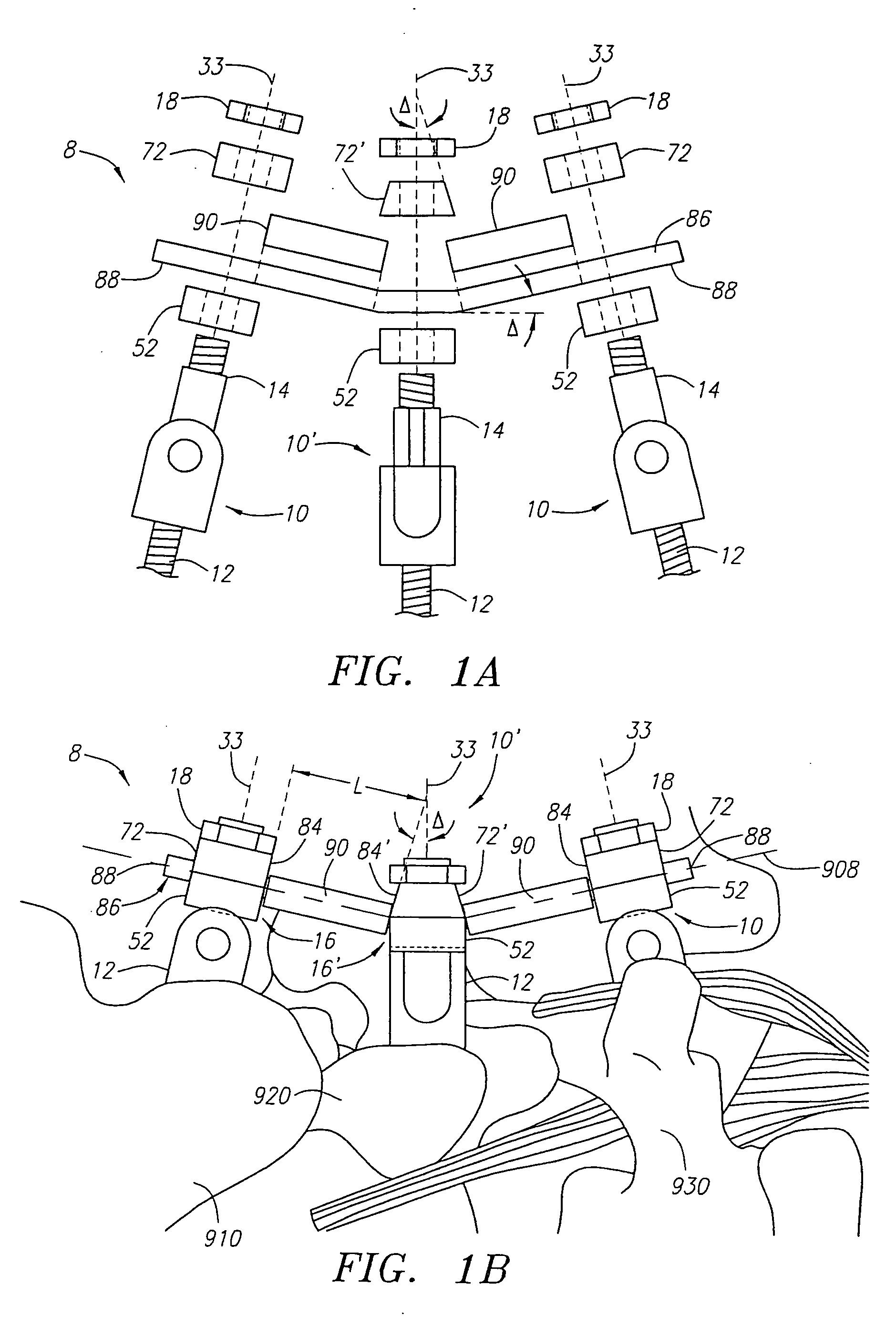
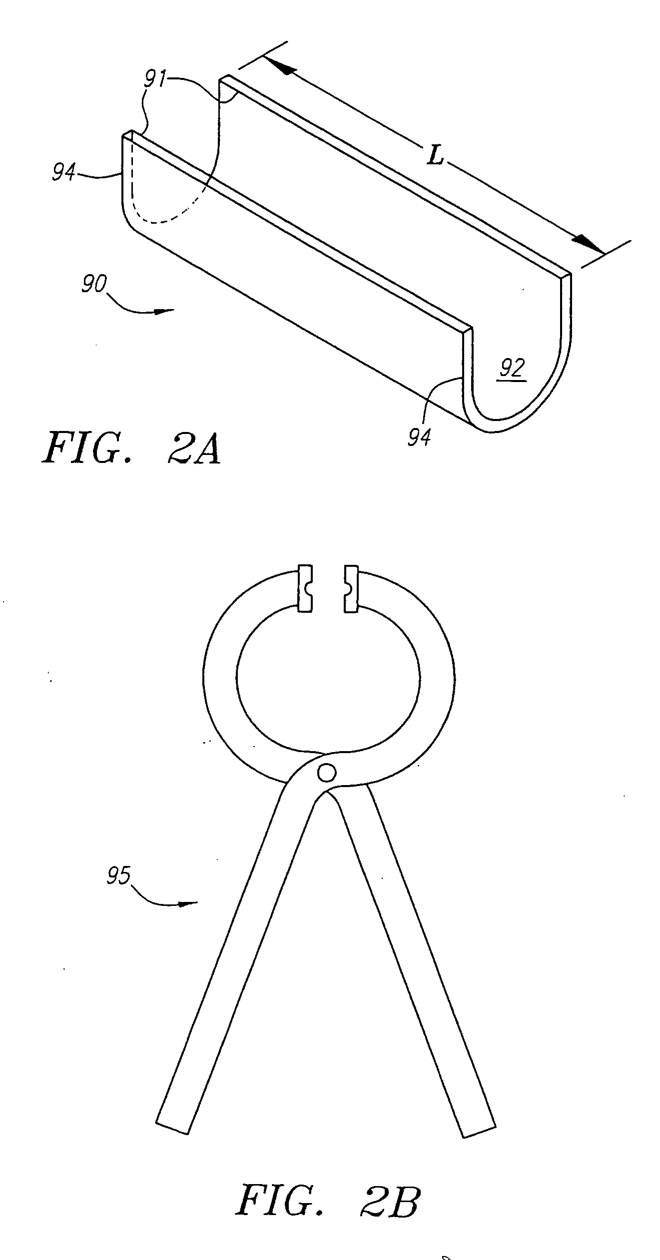
[0081] Turning now to the drawings, FIGS. 1A and 1B show a preferred embodiment of a spinal fixation system 8, in accordance with the present invention. Generally, the system 8 includes a plurality of anchor screw assemblies, 10, a rod 86 securable between the anchor screw assemblies 10, and one or more spacer clips 90 securable to the rod 86. All of the components of the system 8 may be made from a variety of biocompatible materials, e.g., metals, and preferably from titanium or alloys including titanium.
[0082] The rod 86 may be a substantially rigid elongate member, e.g., a solid rod, having a generally round cross-section. Optionally, the rod 86 has one or more flattened regions (not shown) extending between ends 88 of the rod 86. For example, the rod 86 may include opposing flattened regions (not shown), thereby defining a flattened elliptical cross-section. Optionally, the rod 86 may include serrations or teeth (not shown) extending between the ends 88, which may facilitate se...
PUM
Abstract
A spinal fixation system includes a plurality of anchor screw assemblies, e.g. including anchor screws and clamp assemblies defining rod passages therethrough. A rod is receivable in the rod passages between the anchor screw assemblies, and a spacer is securable on the rod. The rod is preferably serrated over less than about 25% of the peripheral surface thereof, and the clamp assemblies preferably include engagement surfaces that include similarly spaced and oriented serrations. During use, a first anchor screw is screwed into a first vertebra, and a second anchor screw is screwed into a second vertebra adjacent the first vertebra, and clamp assemblies are mounted to each anchor screw. A rod is secured between the anchor screw assemblies, thereby fixing a relative spacing of the first and second vertebrae. A spacer may be crimped onto the exposed portion of the rod between the anchor screw assemblies, the spacer extending between the anchor screw assemblies to prevent the anchor screw assemblies, and, consequently, the first and second vertebrae, from moving towards one another.
Description
[0001] This application is a continuation-in-part of U.S. patent application Ser. No. 10 / 698,087, filed Oct. 31, 2003, which application is a continuation-in-part of U.S. patent application Ser. No. 10 / 133,310, filed Apr. 24, 2002. This application is also a continuation-in-part of U.S. patent application Ser. No. 11 / 133,708, filed May 19, 2005, which application is a continuation-in-part of U.S. patent application Ser. No. 10 / 889,754, filed Jul. 12, 2004, which application is a continuation-in-part of U.S. patent application Ser. No. 10 / 698,087, filed Oct. 31, 2003, which application is a continuation-in-part of U.S. patent application Ser. No. 10 / 133,310, filed Apr. 24, 2002, now U.S. Pat. No. 6,770,075, which application is a continuation-in-part of U.S. patent application Ser. No. 09 / 861,278, filed May 17, 2001, now U.S. Pat. No. 6,478,798. The disclosures of each of the foregoing patent applications are expressly incorporated herein by reference.FIELD OF THE INVENTION [0002] Th...
Claims
Application Information
Patent Timeline
Application Date:The date an application was filed.
Publication Date:The date a patent or application was officially published.
First Publication Date:The earliest publication date of a patent with the same application number.
Issue Date:Publication date of the patent grant document.
PCT Entry Date:The Entry date of PCT National Phase.
Estimated Expiry Date:The statutory expiry date of a patent right according to the Patent Law, and it is the longest term of protection that the patent right can achieve without the termination of the patent right due to other reasons(Term extension factor has been taken into account ).
Invalid Date:Actual expiry date is based on effective date or publication date of legal transaction data of invalid patent.
Patent Type & Authority Applications(United States)