
Electromagnetic protection device

A technology of electromagnetic protection and protective cover, which is applied in the direction of electrical components, magnetic field/electric field shielding, local shielding, etc., can solve problems such as unreliable contact, reduce EMC protection effect, increase contact resistance, etc., and achieve the effect of solving poor contact

Active Publication Date: 2021-02-26
HELLA SHANGHAI ELECTRONICS
View PDF17 Cites 0 Cited by
  • Summary
  • Abstract
  • Description
  • Claims
  • Application Information

AI Technical Summary

Problems solved by technology

The existing technology is to fill the gap with conductive elastic material, eliminate the non-conductive point or contact the metal shell and the metal cover through the elastic metal contact piece to form a complete metal shell for electromagnetic shielding, but this electromagnetic protection method is not effective during use. Due to the use environment such as vibration and shock, the contact will not be reliable, so that the electromagnetic signal cannot be well prevented from entering the working space of the electronic device, and good electromagnetic shielding cannot be achieved.
In addition, the effect of this EMC protection has a great relationship with the contact resistance. Due to the surface oxidation of metal parts, the contact resistance will be greatly increased, thereby reducing the EMC protection effect.

Method used


Image

  • Electromagnetic protection device
  • Electromagnetic protection device
  • Electromagnetic protection device

Examples


Embodiment Construction

[0033] The advantages of the present invention will be further elaborated below in conjunction with the accompanying drawings and specific embodiments.

[0034] Reference will now be made in detail to the exemplary embodiments, examples of which are illustrated in the accompanying drawings. When the following description refers to the accompanying drawings, the same numerals in different drawings refer to the same or similar elements unless otherwise indicated. The implementations described in the following exemplary examples do not represent all implementations consistent with the present disclosure. Rather, they are merely examples of apparatuses and methods consistent with aspects of the present disclosure as recited in the appended claims.

[0035] The terminology used in the present disclosure is for the purpose of describing particular embodiments only, and is not intended to limit the present disclosure. As used in this disclosure and the appended claims, the singular...


PUM


Abstract

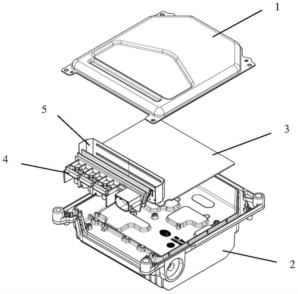
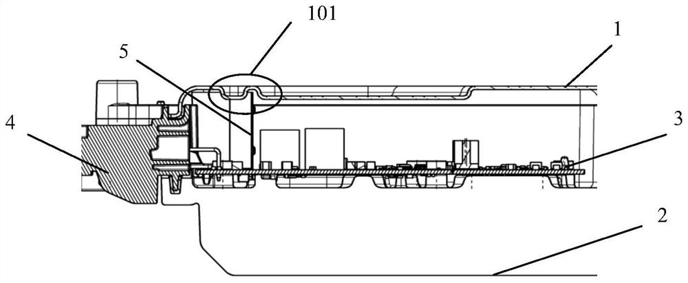
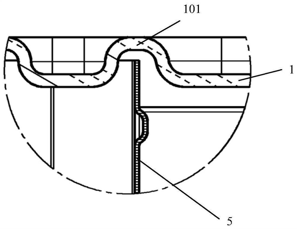
The invention provides an electromagnetic protection device, and the device comprises a protection shell, a protection cover, a protected assembly, a connector and a shielding cover. The protective shell is fixedly connected with the protective cover to form a first space; the protected assembly is located in the first space, and the connector is connected to one end of the protected assembly; theshielding case isolates the protected assembly from the connector; the protective cover is provided with a first protective part close to the shielding cover, the first protective part is provided with at least one groove, and the end, close to the protective cover, of the shielding cover is contained in the first protective part. A second protection part is arranged at the position, close to theshielding cover, of the protection shell and provided with at least one groove, and the end, close to the protection shell, of the shielding cover is contained in the second protection part. According to the technical scheme, the problem of electromagnetic radiation and interference resistance of electronic devices such as electronic devices and PCBs can be effectively solved, and electromagneticprotection is achieved.

Description

technical field [0001] The invention relates to the field of electromagnetic protection, in particular to an electromagnetic protection device. Background technique [0002] Electronic devices, circuit boards and other electronic equipment will be interfered by electromagnetic signals in the surrounding environment during work and cannot work accurately. At the same time, electronic equipment will also radiate electromagnetic waves to the surrounding environment during work, thereby interfering with the normal work of other electronic equipment. Therefore, electronic equipment that has high requirements on signals or is susceptible to interference, such as the field of automotive electronic equipment, generally requires electromagnetic protection design to shield electromagnetic radiation and not radiate electromagnetic waves to ensure stable and accurate operation of the circuit. The principle of electromagnetic shielding is to shield the far field of the radiation interfer...

Claims


Application Information

Patent Timeline
IPC IPC(8): H05K9/00
CPCH05K9/002
Inventor 陈宁宁
Owner HELLA SHANGHAI ELECTRONICS
Learn More