Method, control unit and computer program for controlling milk extraction via an automatic milking machine

A computer program, control unit technology, applied in the field of automatic milking

Inactive Publication Date: 2021-02-26
DELAVAL HLDG AB
View PDF10 Cites 0 Cited by
  • Summary
  • Abstract
  • Description
  • Claims
  • Application Information

AI Technical Summary

Problems solved by technology

[0005] However, it has been shown that none of the known solutions provides a fully satisfactory milking in terms of efficiency and responsiveness to the animal's milking process

Method used


Image

  • Method, control unit and computer program for controlling milk extraction via an automatic milking machine
  • Method, control unit and computer program for controlling milk extraction via an automatic milking machine
  • Method, control unit and computer program for controlling milk extraction via an automatic milking machine

Examples


Embodiment Construction

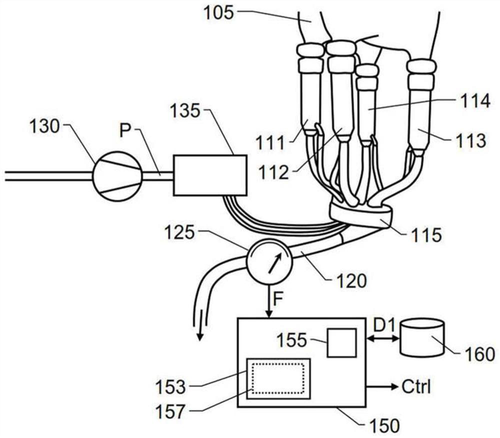
[0032] figure 1 Shown is a milking cluster for udder milking, ie where milk is extracted jointly from all teats of the animal udder 105 based on pressure variations common to all teats. Here, the pulsation controller 135 is arranged to control the pulsating vacuum from the vacuum pump 130 to be repeatedly applied to the pulsation chamber formed between each teatcup and its respective liner therein. The milking claws 115 are connected in a set of four teatcups 111 , 112 , 113 and 114 to the teat receiving cavity by respective milk hoses. Teat cups 111 , 112 , 113 and 114 are in turn attached to respective teats of breast 105 . The pulsation controller 135 is configured to apply a pulsating vacuum to all four teatcups 111 , 112 , 113 and 114 while there is a milking vacuum in the milk hose. Milk is extracted from the udder 105 , drawn by the milking vacuum, collected in the milking claw 115 and forwarded through the milk duct 120 . The flow meter 125 records a parameter repre...


PUM


Abstract

An automatic milking machine extracts milk from the teats of an animal by applying a milking vacuum to a respective teat receiving cavity (111, 112, 113, 114) each in which one of the teats is locatedduring a milking session (TM). The milking session (TM) includes a boost phase (TBOOST) and is concluded by an exit phase (TEXIT). During the boost phase (TBOOST), the milking vacuum is applied at anelevated pressure level. During the exit phase, the milking vacuum is applied at one or more levels, each of which is lower than the elevated pressure level. The operation of the automatic milking machine transitions from the boost phase (TBOOST) to the exit phase (TEXIT) when (t2) a temporal criterion is fulfilled.

Description

technical field [0001] The present invention generally relates to automatic milking of dairy animals. More specifically, the present invention relates to a control unit for a milking system and a method of controlling a milking system. The invention also relates to a computer program and a non-volatile data carrier. Background technique [0002] With the development of new and more advanced milking equipment, the milking process has become almost completely automated. For reasons of efficiency and animal health, it is important to optimally control milk extraction throughout the milking session. Controlling the milking machine in an appropriate way for a particular animal between different milking occasions is never an easy task as milk flow characteristics vary widely between different animals. [0003] There are known solutions for controlling a milking machine based on the flow of extracted milk as a function of time. For example, DE3609275A1 describes a milking metho...

Claims


Application Information

Patent Timeline
Patent Type & Authority Applications(China)
IPC IPC(8): A01J5/007
CPCA01J5/007A01J5/0075A01J5/01A01J5/047A01J7/025A01J7/04
Inventor C.O.保尔鲁德
Owner DELAVAL HLDG AB
Why Eureka
Try Eureka