Machine tool

A technology of machine tool and holding mechanism, which is applied in the direction of metal processing machinery parts, accessories of tool holders, metal processing equipment, etc.

Pending Publication Date: 2021-02-26
DMG MORI SEIKI CO LTD
View PDF1 Cites 0 Cited by
  • Summary
  • Abstract
  • Description
  • Claims
  • Application Information

AI Technical Summary

Problems solved by technology

[0016] However, conventionally, in the machine tool provided with the timer and the jig control unit disclosed in the above-mentioned Patent Document 1, it is still unsolved that the operator cannot perform the work in a sufficiently prepared posture when installing or removing the tool from the spindle. The operation of this question

Method used


Image

  • Machine tool
  • Machine tool
  • Machine tool

Examples


Embodiment Construction

[0047] Hereinafter, specific embodiments of the present invention will be described with reference to the drawings.

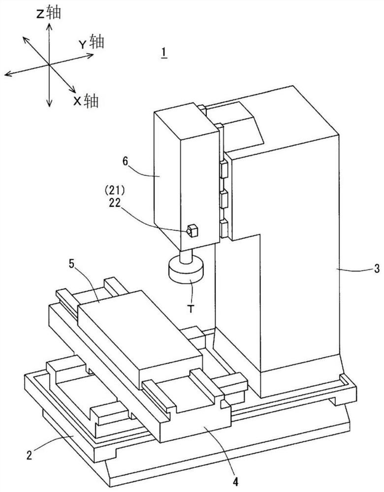
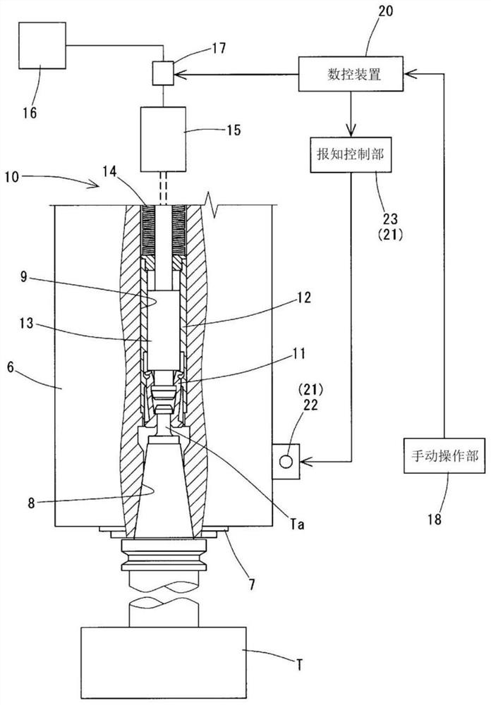
[0048] like figure 1 As shown, the machine tool 1 of this example is a vertical machining center, possessing the figure 1 The machine base 2 shown, the column 3 erected on the machine base 2, the bed saddle 4 that can be moved on the machine base 2 in the Y-axis direction, and the bed saddle 4 that can be moved in the X-axis direction The table 5 on the top, and the spindle head 6 supported on the column 3 in a movable manner in the Z-axis direction, and figure 2 The manual operation part 18, the numerical control device 20, the hesitation state notification part 21, etc. are shown. In addition, the X-axis, Y-axis, and Z-axis are moving axes orthogonal to each other, and the Z-axis is a vertical axis.

[0049] like figure 2 As shown, the spindle head 6 holds the spindle 7 and the spindle 7 can rotate around the vertical axis. A tapered mounting hole (hol...


PUM


Abstract

A machine tool (1) is provided with: a holding unit (7) for holding a tool (T); a holding mechanism (10) which performs a holding operation for holding the tool (T) in the holding unit (7) and a releasing operation for releasing the tool from the holding unit (7); a control unit (20) for making the holding mechanism (10) perform the holding operation and the releasing operation; a manual operationunit (18) for inputting a manual operation signal to the control unit (20); and a postponement state notification unit (21). The control unit (20) receives the operation signal from the manual operation unit (18), and then transmits a drive signal, corresponding to the operation signal, to the holding mechanism (10) after a predetermined postponement time elapses, and thereby makes the holding mechanism operate. The postponement state notification unit (21) is provided with an energy output apparatus (22) for outputting human-sensible energy, recognizes the remaining postponement time on thebasis of the information received from the control unit, and provides notification of the information according to the remaining time by changing the output state of the energy output apparatus (22).

Description

technical field [0001] The present invention relates to a machine tool that has a holding portion for holding a tool, and is configured such that a tool can be manually attached to or removed from the holding portion. Background technique [0002] For example, a machine tool such as a machining center (machining center) is configured such that a tool is held on a spindle, and the spindle and a suitable table on which a workpiece is mounted face each other in three-dimensional space while the spindle is being rotated by a spindle motor. Move to process the workpiece. [0003] In addition, a holding mechanism for holding a tool in a holding hole of the main shaft is provided on the main shaft. The holding mechanism is controlled by an appropriate control device such as a numerical control device, and executes a holding operation for holding the tool and a releasing operation for releasing the held tool. [0004] In addition, such machine tools are often configured so that too...

Claims


Application Information

Patent Timeline
Patent Type & Authority Applications(China)
IPC IPC(8): B23B31/00B23Q17/00
CPCB23Q17/00
Inventor 饭山浩司
Owner DMG MORI SEIKI CO LTD
Why Eureka
Try Eureka