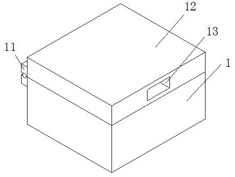
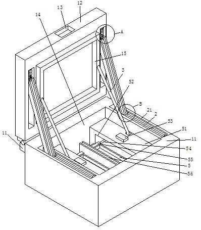
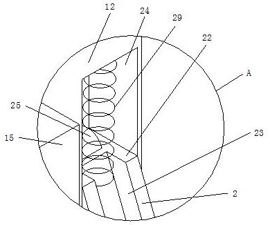
Anesthesia instrument placing box for anesthesia department

A technology for placing boxes and anesthesia departments, which is applied in the field of medical equipment, can solve the problems that the anesthesia placing box cannot be opened normally, increase the weight of the anesthesia placing box, and make it inconvenient for doctors to find anesthesia equipment quickly, so as to avoid the increase of the weight of the box, and quickly Easy to take and carry

Active Publication Date: 2021-03-02
THE AFFILIATED HOSPITAL OF SHANDONG UNIV OF TCM
View PDF21 Cites 2 Cited by
  • Summary
  • Abstract
  • Description
  • Claims
  • Application Information

AI Technical Summary

Problems solved by technology

[0004] Aiming at the deficiencies in the prior art, the present invention provides an anesthesia appliance storage box for the department of anesthesiology, which has the advantages of avoiding the lifting of the weight of the box, achieving the effect that the anesthesia appliance can be quickly taken and used while being convenient for doctors to carry, and solves the problem of The addition of a drive motor to the anesthesia placement box will greatly increase the weight of the anesthesia placement box, and the doctor also needs to use a specific switch to open the anesthesia placement box, so when the drive motor is damaged, it may cause the anesthesia placement box to be damaged. The situation that it cannot be opened normally occurs, and the anesthesia storage box puts the anesthesia equipment together, which is not convenient for the doctor to quickly find the anesthesia equipment that needs to be used.

Method used


Image

  • Anesthesia instrument placing box for anesthesia department
  • Anesthesia instrument placing box for anesthesia department
  • Anesthesia instrument placing box for anesthesia department

Examples


Embodiment Construction

[0034] The present invention will be described in further detail below in conjunction with accompanying drawing, and wherein same parts and components are represented by same reference sign, and it should be noted that words " front ", " rear ", " left ", " right " used in the following description , "upper" and "lower", "bottom" and "top" refer to directions in the drawings, and the words "inner" and "outer" refer to directions toward or away from the geometric center of a particular component, respectively.

[0035] The following will clearly and completely describe the technical solutions in the embodiments of the present invention with reference to the accompanying drawings in the embodiments of the present invention. Obviously, the described embodiments are only some, not all, embodiments of the present invention. Based on the embodiments of the present invention, all other embodiments obtained by persons of ordinary skill in the art without making creative efforts belong ...


PUM


Abstract

The invention relates to the technical field of medical instruments, and discloses an anesthesia instrument placement box for the anesthesia department. The anesthesia instrument placement box comprises a box body, an inner groove is formed in the upper surface of the box body, and anesthesia instrument placement mechanisms for placing anesthesia instruments are arranged on the two sides of the interior of the inner groove; an automatic opening and closing mechanism which is convenient to automatically control opening and closing is arranged in each anesthesia instrument placing mechanism; byarranging the automatic switch mechanism and the anesthetic instrument placing mechanisms, when a doctor opens the cover plate on the box body, the two instrument placing plates can be automatically driven to move the anesthetic instruments out of the two rectangular grooves into the inner grooves, by arranging the two symmetrical instrument placing plates, the doctor can place different anesthesia instruments into the two instrument placing plates in a classified mode, so that the doctor can rapidly take out the anesthesia instruments when opening the box body, meanwhile, no extra driving force is arranged, the weight of the box body can be prevented from being increased, and the effects that the doctor can carry the box conveniently, and the anesthetic instruments can be rapidly taken for use can be achieved.

Description

technical field [0001] The invention relates to the technical field of medical devices, in particular to an anesthesia device storage box for anesthesiology department. Background technique [0002] Anesthesiology is a comprehensive discipline, which includes multidisciplinary knowledge and a wide range. It not only meets the requirements of surgery, but also participates in the rescue work of various departments, gynecological painless childbirth, painless abortion, etc. Anesthesiologists Anesthesia apparatus is required to anesthetize patients, and before use, the anesthesia apparatus is placed in an anesthesia storage box in order to ensure that it will not be affected by bacteria in the outside air. The existing patent No. CN11811861A proposes an anesthesia apparatus that is convenient for use in anesthesiology departments The placement box is equipped with structures such as a drive motor, a reciprocating screw, a coil, a moving rod and a connecting rod, wherein the rot...

Claims


Application Information

Patent Timeline
Patent Type & Authority Applications(China)
IPC IPC(8): A61B50/31
CPCA61B50/31A61B2050/311A61B2050/005A61B2050/0051A61B2050/0057A61B2050/0066
Inventor 林常森
Owner THE AFFILIATED HOSPITAL OF SHANDONG UNIV OF TCM
Why Eureka
Try Eureka