Constant-temperature reaction container and constant-temperature method

A technology for a reaction vessel and a reactor, applied in the field of reactors, can solve the problems of easy loss when removing and placing, experiment failure, and the trouble of increasing fixed vessels, and achieves the effects of reducing liquid evaporation, preventing experiment failure, and improving the effect of constant temperature.

Pending Publication Date: 2021-03-02
KUNMING UNIV OF SCI & TECH
View PDF5 Cites 0 Cited by
  • Summary
  • Abstract
  • Description
  • Claims
  • Application Information

AI Technical Summary

Problems solved by technology

[0002] In the prior art, the upper cover of the constant temperature stirrer pot is equipped with combined ferrules of different calibers, also called annular pot covers, which can be adapted to reaction vessels of different calibers, but the combined ferrules of different calibers are more troublesome to use and are often easy to scatter , and it is not easy to place, and it is easy to lose if it is removed and placed improperly
When the laboratory is heated in a water bath, because the stirrer pot does not consider how to stabilize the reaction vessel in the boiling water bath, it mostly relies on the weight of the vessel itself to maintain a stable state in the boiling water; when the sample volume in the vessel is too small, it will cause the vessel to Rolled over under the buoyancy of the water bath, resulting in the failure of the experiment,
The final result will not only increase the trouble of fixing the container for the staff, but also affect the stability of the entire experiment and the accuracy of the experimental results

Method used


Image

  • Constant-temperature reaction container and constant-temperature method
  • Constant-temperature reaction container and constant-temperature method
  • Constant-temperature reaction container and constant-temperature method

Examples


Embodiment 1

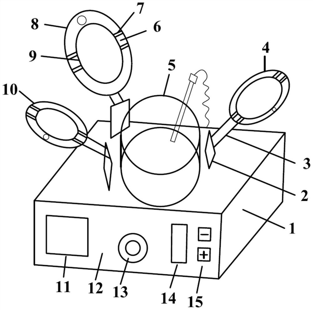
[0027] Embodiment 1: as figure 1 and 2 As shown, a constant temperature reaction vessel includes a magnetic stirrer 1, a constant temperature liquid bath 5, a combined collar member, a temperature sensor and a reactor, the constant temperature liquid bath 5 is fixedly arranged at the center of the top of the magnetic stirrer 1, and the reactor The bottom end is arranged on the magnetic surface at the top of the magnetic stirrer 1, the bottom of the reactor is arranged in the constant temperature liquid bath 5, the combined collar member is arranged on the top of the constant temperature liquid bath 5, and the combined collar member is provided with a positioning piece, The top of the constant temperature liquid bath 5 reactor is fixedly arranged on the combined collar member through a positioning piece, and the temperature sensor passes through the combined collar member and extends into the reactor;

[0028]The bottom end of the magnetic surface of the magnetic stirrer 1 is ...

Embodiment 2

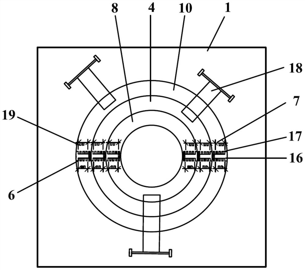
[0032] Embodiment 2: the constant temperature reaction vessel of this embodiment is basically the same as the constant temperature reaction vessel of embodiment 1, the difference is: as Figure 1-3 As shown, the combined collar components include collar I4, collar II8 and collar III10. When combined, collar I4, collar II8 and collar III10 are concentric rings, and the outer diameter of collar III10 is equal to the constant temperature liquid bath The outer diameter of the pot 5, the inner diameter of the collar I4 is equal to the outer diameter of the collar II8, the inner diameter of the collar II8 is equal to the outer diameter of the collar III10, the collar I4 is connected with a connecting rod I3, and the other end of the connecting rod I3 rotates Set on the top of the support rod I2, the bottom end of the support rod I2 is fixed on the housing of the magnetic stirrer 1, the collar II8 is connected with the connecting rod II18, and the other end of the connecting rod II18 ...

Embodiment 3

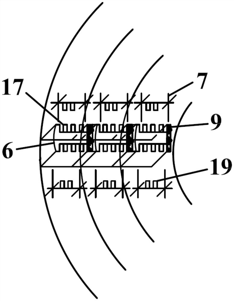
[0040] Embodiment 3: The constant temperature reaction vessel of this embodiment is basically the same as the constant temperature reaction vessel of Example 2, the difference is that: the height of the collar I4, the collar II8 and the collar III10 are the same and the top surface is located on the same horizontal plane, and the level is smooth The top surfaces of block I, horizontal slider II, horizontal slider III6, horizontal slider IV, horizontal slider V and horizontal slider VI are on the same level and higher than the top surface of collar I4, horizontal slider I, horizontal The top side walls of the slider II, the horizontal slider III6, the horizontal slider IV, the horizontal slider V and the horizontal slider VI are all provided with locking teeth I17;

[0041] Both sides of horizontal chute I are provided with vertical chute I, both sides of horizontal chute II16 are provided with vertical chute II, both sides of horizontal chute III are provided with vertical chut...


PUM


Abstract

The invention relates to a constant-temperature reaction container and a constant-temperature method, belonging to the technical field of reactors. The constant-temperature reaction container comprises a magnetic stirrer, a constant-temperature liquid bath pot, a combined lantern ring component, a temperature sensor and a reactor, wherein the constant-temperature liquid bath pot is fixedly arranged in the center of the top end of the magnetic stirrer; the bottom end of the reactor is arranged on the magnetic surface of the top end of the magnetic stirrer; the bottom of the reactor is arrangedin the constant-temperature liquid bath pot; the combined lantern ring component is arranged at the top of the constant-temperature liquid bath pot; a positioning piece is arranged on the combined lantern ring component; the top of the constant-temperature liquid bath pot reactor is fixedly arranged on the combined lantern ring component through the positioning piece; and the temperature sensor penetrates through the combined lantern ring component and extends into the reactor. According to the invention, the temperature in the reactor is monitored in real time through the temperature sensor,and constant temperature is achieved; and positioning and stabilization of the reactor are achieved through the positioning piece of the combined lantern ring component, and experiment failure causedby tipping of the reaction container is prevented.

Description

technical field [0001] The invention relates to a constant temperature reaction container and a constant temperature method, belonging to the technical field of reactors. Background technique [0002] In the prior art, the upper cover of the thermostatic stirrer pot is equipped with combined ferrules of different calibers, also called annular pot covers, which can be adapted to reaction vessels of different calibers, but the combined ferrules of different calibers are more troublesome to use and are often easy to scatter , and it is not easy to place, and it is easy to lose if it is removed and placed improperly. When the laboratory is heated in a water bath, because the stirrer pot does not consider how to stabilize the reaction vessel in the boiling water bath, it mostly relies on the weight of the vessel itself to maintain a stable state in the boiling water; when the sample volume in the vessel is too small, it will cause the vessel to Rolled over under the buoyancy of ...

Claims


Application Information

Patent Timeline
Patent Type & Authority Applications(China)
IPC IPC(8): B01J19/18B01L7/02B01L9/00
CPCB01J19/18B01J19/0066B01J19/0053B01J19/0013B01L7/02B01L9/00B01J2219/00099B01L2200/023
Inventor 夏洪应辛椿福张利波张威曾抗庆蔡无尘徐英杰蒋桂玉张奇严恒
Owner KUNMING UNIV OF SCI & TECH
Why Eureka
Try Eureka