
Disc clamping device and using method thereof

A technology of clamping device and disc, which is applied in the direction of positioning device, clamping, support, etc., can solve the problems of taking a long time and reducing product processing efficiency, and achieve the effect of reducing time, improving processing efficiency and saving manufacturing cost

Active Publication Date: 2021-03-02
杭州精伟科技有限公司
View PDF8 Cites 2 Cited by
  • Summary
  • Abstract
  • Description
  • Claims
  • Application Information

AI Technical Summary

Problems solved by technology

[0002] When performing drilling and other processing on disc-shaped products, it is necessary to clamp and fix the disc-shaped products first to prevent the disc-shaped products from loosening during processing and resulting in insufficient processing accuracy. However, the disc clamps in the prior art When clamping the fixture, only one disc-shaped product can be clamped, and it is generally clamped manually. It will take a long time to complete the loading and unloading of a product, which greatly reduces the processing efficiency of the product.

Method used


Image

  • Disc clamping device and using method thereof
  • Disc clamping device and using method thereof
  • Disc clamping device and using method thereof

Examples


Embodiment Construction

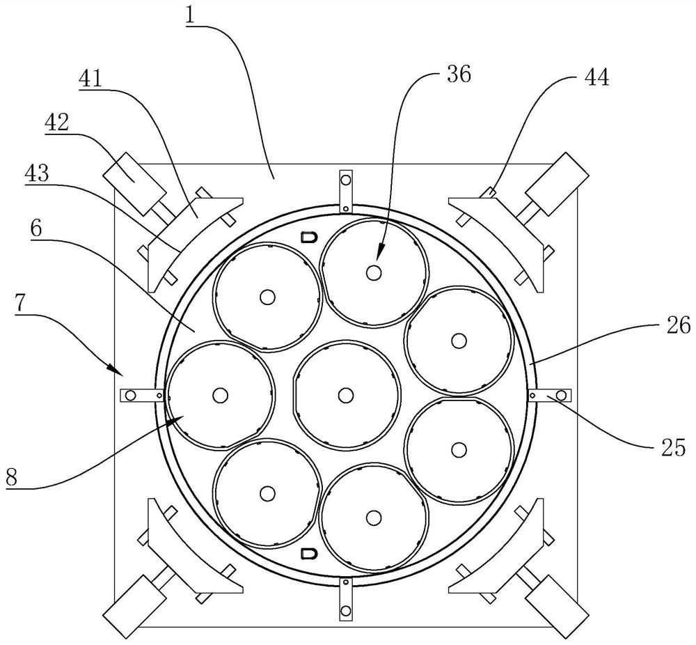
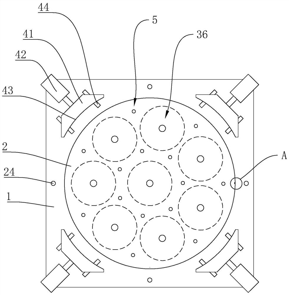
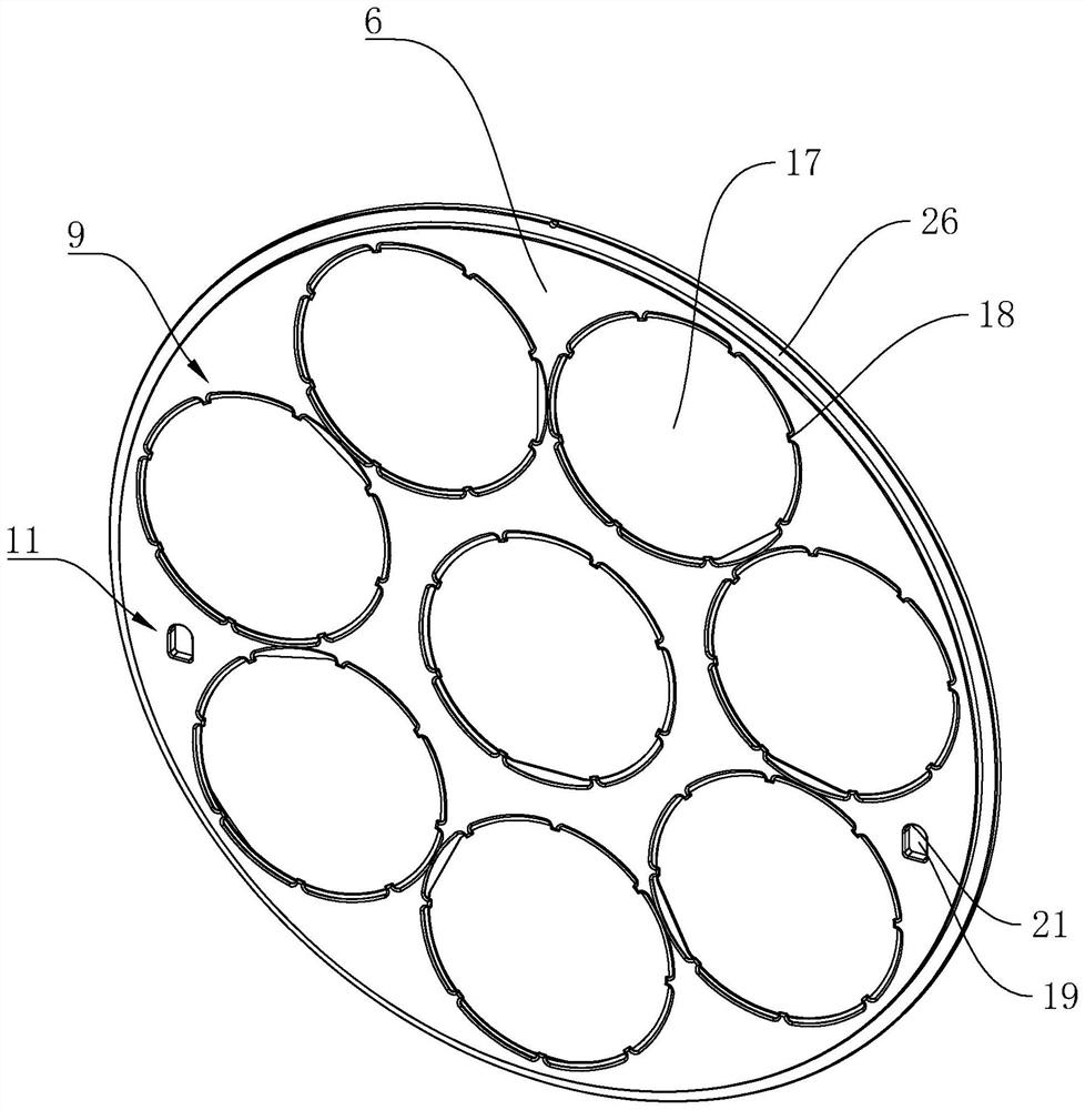
[0038] like Figure 1-Figure 7 As shown, a disc clamping device includes a base 1, the base 1 is provided with a lower chuck groove 2, and the lower chuck groove 2 is detachable through the lower chuck circumferential limit structure 3 The lower chuck 4 is provided, and the bottom of the lower chuck groove 2 is also provided with a lower chuck fixing assembly 5, and the base 1 is also provided with an upper chuck 6 and can drive the upper chuck 6 along the vertical direction. The upper chuck driving mechanism 7 that lifts in the vertical direction, the upper chuck 6 is located on the upper side of the lower chuck 4, and the upper chuck 6 and the lower chuck 4 are combined to form several disc clamping grooves 8.

[0039] In this embodiment, several disk clamping grooves 8 formed by the combination of the upper chuck 6 and the lower chuck 4 can clamp and fix multiple disk-shaped products at one time, and the upper chuck driving mechanism 7 can drive the upper chuck The disc mo...


PUM


Abstract

The invention provides a disc clamping device and a using method thereof, and belongs to the technical field of clamps. The disc clamping device comprises a base, a lower chuck groove is formed in thebase, a lower chuck is detachably arranged in the lower chuck groove through a lower chuck circumferential limiting structure, a lower chuck fixing assembly is further arranged at the bottom of the lower chuck groove, the base is further provided with an upper chuck and an upper chuck driving mechanism capable of driving the upper chuck to ascend and descend in the vertical direction, the upper chuck is located on the upper side of the lower chuck, and the upper chuck and the lower chuck are combined to form a plurality of disc clamping grooves. The multiple disc clamping grooves formed by combining the upper chuck and the lower chuck can clamp and fix a plurality of disc-shaped products at a time, the upper chuck driving mechanism can drive the upper chuck to move to achieve automatic clamping and loosening, the time spent on feeding and discharging during product machining is greatly shortened, and therefore the machining efficiency of the products is effectively improved.

Description

technical field [0001] The invention belongs to the technical field of clamps, and relates to a disk clamping device and a using method thereof. Background technique [0002] When performing drilling and other processing on disc-shaped products, it is necessary to clamp and fix the disc-shaped products first to prevent the disc-shaped products from loosening during processing and resulting in insufficient processing accuracy. However, the disc clamps in the prior art When clamping the fixture, only one disc-shaped product can be clamped, and it is generally clamped manually. It will take a long time to complete the loading and unloading of a product, which greatly reduces the processing efficiency of the product. . [0003] In order to overcome the deficiencies of the prior art, people have proposed various solutions through continuous exploration, such as a Chinese patent disclosing a disc punching fixture [Application No.: 201410680032.0], including a base and a push rod ...

Claims


Application Information

Patent Timeline
Patent Type & Authority Applications(China)
IPC IPC(8): B23B47/00B23Q3/06
CPCB23B47/00B23Q3/06B23Q3/062
Inventor 董江荣卢圣波陆成福任威力芦凤吕
Owner 杭州精伟科技有限公司
Learn More