
Leg mechanism and quadruped robot

A leg mechanism and drive mechanism technology, applied in the direction of motor vehicles, transportation and packaging, etc., can solve the problems of inability to stretch, low terrain passability, poor shock absorption effect, etc., to improve terrain passability, enhance buffering capacity, good protection effect

Pending Publication Date: 2021-03-02
GUANGDONG UNIV OF TECH
View PDF1 Cites 2 Cited by
  • Summary
  • Abstract
  • Description
  • Claims
  • Application Information

AI Technical Summary

Problems solved by technology

[0004] The purpose of the present invention is to overcome the disadvantages of the existing leg mechanism, such as fixed calf structure, inability to stretch, relatively low terrain passability, poor shock absorption effect, and high maintenance cost, and provide a leg mechanism

Method used


Image

  • Leg mechanism and quadruped robot
  • Leg mechanism and quadruped robot
  • Leg mechanism and quadruped robot

Examples


Embodiment 1

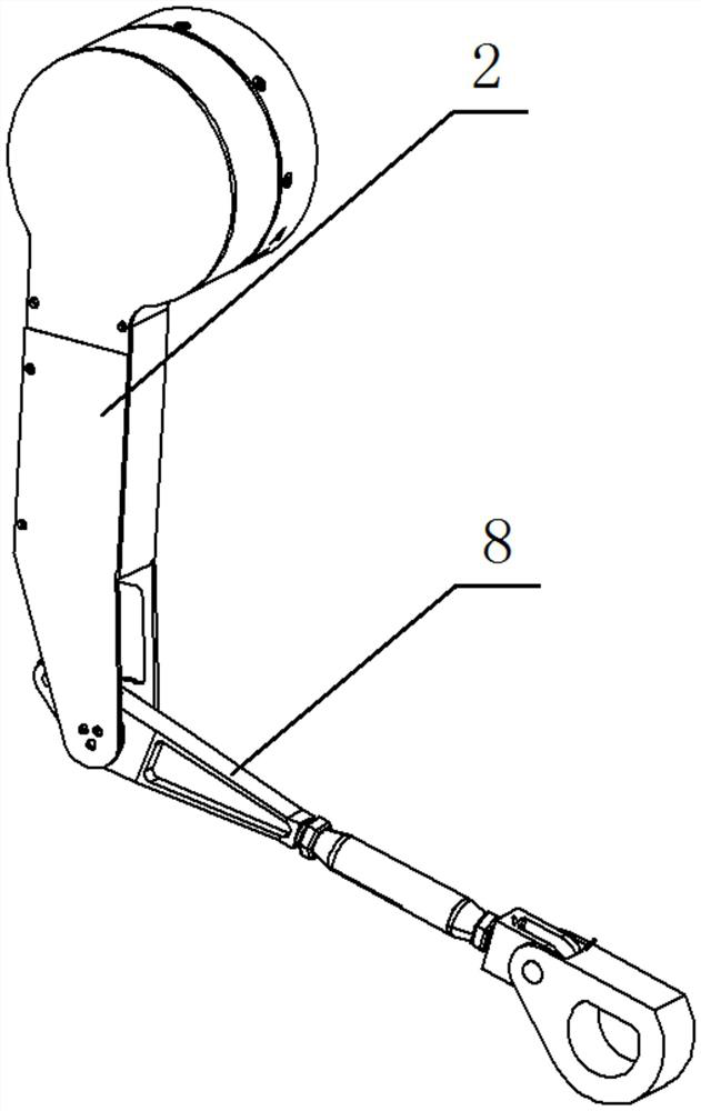
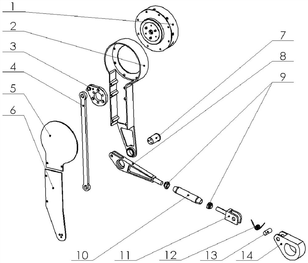
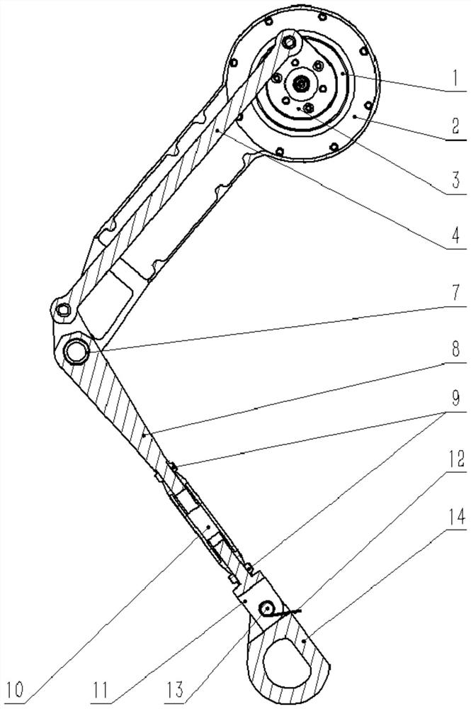
[0027] Such as Figure 1 to Figure 3 Shown is an embodiment of a leg mechanism of the present invention. A leg mechanism, the leg mechanism includes a thigh 2 and a calf hinged by a rotating shaft 7, a driving mechanism is provided on the thigh 2, the driving mechanism is connected with the calf through the first rod 4, and the driving mechanism drives the calf through the first rod 4. For sports, the end of the calf is provided with a flexibly connected foot module 14, and the calf is provided with a telescopic adjustment structure, which can telescopically adjust the length of the calf to adapt to different degrees of rough terrain and obstacles of different sizes.

[0028] In this embodiment, the thigh 2 also includes a housing, the housing is formed by splicing the first thigh housing 5 and the second thigh housing 6, the driving mechanism penetrates into the housing, the first rod 4 is located inside the housing, and the driving The mechanism includes a motor 1 and a mot...

Embodiment 2

[0033] This embodiment is similar to Embodiment 1, the difference is that the side of the lifting ear 11 close to the sole module 14 is provided with a limiter, one end of the limiter is a right angle, the other end of the limiter is an arc angle, and the sole module 14 The side connected to the lifting lug limiter is a straight line, and the length of the straight line is greater than the length of the limiter. When the sole module 14 rotates around the spring pin 13, the straight edge of the sole module can surround the limiter. The arc angle is rotated, and the right angle of the stopper will be against the straight edge of the sole module 14 to limit the rotation of the sole module 14 .

[0034]Wherein, the limiting member enables the rotation range of the sole module 14 and the lifting ear 11 to be 0°-90°. The sole module 14 is wrapped with polyurethane rubber for shock absorption. When the sole module 14 touches the ground, the polyurethane rubber wrapped outside can red...

Embodiment 3

[0037] An embodiment of a quadruped robot. A quadruped robot, including four leg mechanisms of embodiment 2 in the quadruped robot, the leg mechanism can adjust the overall height of the quadruped robot, can adapt to terrains of different ruggedness and obstacles of different heights, and can The terrain passing ability of the quadruped robot is improved, and there is no need to be equipped with various robot spare parts and models. The sole module 14 adopts a simple mechanism and uses a spring to realize the shock absorption function, which enhances the buffering capacity of the quadruped robot, and is suitable for the quadruped robot. The precision components provide better protection.


PUM


Abstract

The invention provides a leg mechanism which comprises a thigh and a shank which are hinged to each other, a driving mechanism is arranged on the thigh, the driving mechanism is connected with the shank through a first rod, a rotationally connected sole module is arranged at one end of the shank, and the shank comprises a telescopic adjusting mechanism. The invention further provides the quadrupedrobot. The structure of the leg mechanism is improved, so that when the leg mechanism faces different terrains and obstacles, the length of the legs can be adjusted, parts do not need to be replaced,the damping requirement is met, and maintenance is easy.

Description

technical field [0001] The present invention relates to the technical field of quadruped robots, and more specifically, to a leg mechanism and a quadruped robot. Background technique [0002] Existing wheeled and tracked vehicles can only reach about half of the Earth's landmass, while quadruped robots can reach a much larger area of ​​land. Quadruped robots have better passability than wheels or tracks in rough terrain, and can be used to replace people to complete tasks such as observation patrols in dangerous areas, harsh environments, and rough terrain, and material transportation. [0003] The most similar implementation to the present invention: Chinese Patent Publication No. CN111232088A, published on June 5, 2020, a leg mechanism of a quadruped robot and a quadruped robot. The leg mechanism includes mutually articulated thighs and shanks, The upper end of the thigh is equipped with a motor casing and a planetary reduction mechanism. A motor stator and a motor rotor ...

Claims


Application Information

Patent Timeline
IPC IPC(8): B62D57/032
CPCB62D57/032
Inventor 李俊陈永添何仲衡吴元清鲁仁全
Owner GUANGDONG UNIV OF TECH
Learn More