
Flying device

An artifact, parallel arrangement technology, applied in the field of aircraft, can solve the problems of inability to freely change the flight direction of the aircraft, technical difficulties of flapping rotor aircraft, poor lift stability, etc., to achieve good application prospects, ensure smooth takeoff, and easy to operate.

Inactive Publication Date: 2021-03-02
FOSHAN SHENFENG AVIATION SCI & TECH
View PDF0 Cites 0 Cited by
  • Summary
  • Abstract
  • Description
  • Claims
  • Application Information

AI Technical Summary

Problems solved by technology

[0002] The flapping rotorcraft is an aircraft manufactured by imitating the flight of birds. It uses flapping wing surfaces like the wings of birds to generate lift and pulling force. At present, although many experts and scholars at home and abroad have carried out A large amount of research and experiment, but, because existing many flapping rotorcrafts can cause the lift offset that produces during rotor up and down operation process, make the development of flapping rotorcrafts still exist many technical difficulties, thus also just cause existing Flapping rotorcrafts have poor lift stability, low safety, and poor flexibility, and cannot freely change the flight direction of the aircraft

Method used


Image

  • Flying device
  • Flying device
  • Flying device

Examples


Embodiment Construction

[0048] Embodiments of the present invention are described in detail below, examples of which are shown in the drawings, wherein the same or similar reference numerals designate the same or similar elements or elements having the same or similar functions throughout. The embodiments described below by referring to the figures are exemplary and are intended to explain the present invention and should not be construed as limiting the present invention.

[0049] In describing the present invention, it is to be understood that the terms "upper", "lower", "front", "rear", "left", "right", "vertical", "horizontal", "top", The orientation or positional relationship indicated by "bottom", "inner", "outer", etc. is based on the orientation or positional relationship shown in the drawings, and is only for the convenience of describing the present invention and simplifying the description, rather than indicating or implying the referred device or positional relationship. Elements must hav...


PUM


Abstract

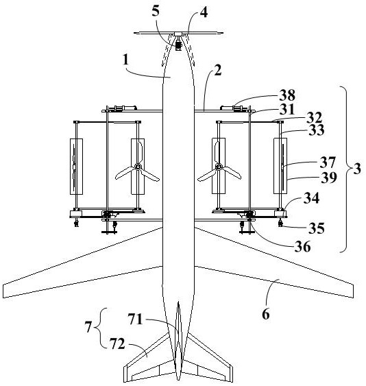
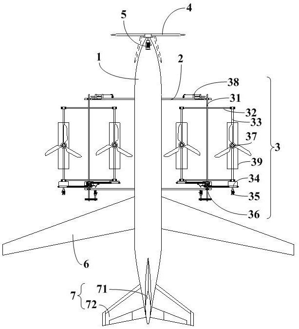
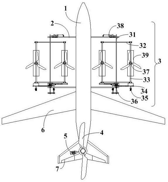
The invention discloses a flying device which comprises a device body, a supporting assembly and a flapping rotor wing assembly, the flapping rotor wing assembly comprises two sets of flapping rotor wing devices, the two sets of flapping rotor wing devices are symmetrically arranged on the two sides of the drone body through the supporting assembly, and each set of flapping rotor wing device comprises a revolution main shaft, a rotating arm, a rotation main shaft, a rotating wheel, a driving part, a clutch and a rotor wing part. According to the ornithopter rotor wing device, through linkage cooperation of the revolution main shaft, the rotating arm, the autorotation main shaft, the rotating wheel, the driving part, the clutch and the rotor wing part, the revolution main shaft in the ornithopter rotor wing device drives the rotating arm and the autorotation main shaft to revolve, and the autorotation main shaft can also rotate in the revolution process through the arrangement of the rotating wheel; when one rotor part of the flapping rotor wing device rotates to a horizontal state, the clutch is closed, and the second driving motor is started to drive the other autorotation main shaft and the rotor wing part to autorotate until the other autorotation main shaft and the rotor wing part rotate to the horizontal state, so that the four rotor wing parts are all in the horizontal state, and larger lift force is provided for take-off and hovering of the aircraft.

Description

technical field [0001] The present invention relates to the technical field of aircraft, and more specifically relates to a flying artifact. Background technique [0002] The flapping rotorcraft is an aircraft manufactured by imitating the flight of birds. It uses flapping wing surfaces like the wings of birds to generate lift and pulling force. At present, although many experts and scholars at home and abroad have carried out A large amount of research and experiment, but, because existing many flapping rotorcrafts can cause the lift offset that produces during rotor up and down operation process, make the development of flapping rotorcrafts still exist many technical difficulties, thus also just cause existing Flapping rotorcrafts have poor lift stability, low safety, and poor flexibility, and cannot freely change the flight direction of the aircraft. [0003] Therefore, it is an urgent need for those skilled in the art to provide a flying artifact with reasonable design,...

Claims


Application Information

Patent Timeline
IPC IPC(8): B64C27/22B64C27/32B64C33/02
CPCB64C27/22B64C27/32B64C33/02
Inventor 王志成
Owner FOSHAN SHENFENG AVIATION SCI & TECH
Learn More