
Sensor device

A sensor device and sensor technology, applied in the direction of sensors, caliper sensors, mechanical equipment, etc., can solve problems such as time-consuming, and achieve the effect of reducing production time, fast and instant identification, and reducing the amount of particulate matter

Pending Publication Date: 2021-03-02
STURM MASCH & ANLAGENBAU GMBH
View PDF7 Cites 0 Cited by
  • Summary
  • Abstract
  • Description
  • Claims
  • Application Information

AI Technical Summary

Problems solved by technology

Overall, this saves material and time, as uneven layer thicknesses would otherwise have to be removed or leveled in a subsequent grinding process, which is time consuming

Method used


Image

  • Sensor device
  • Sensor device
  • Sensor device

Examples


Embodiment Construction

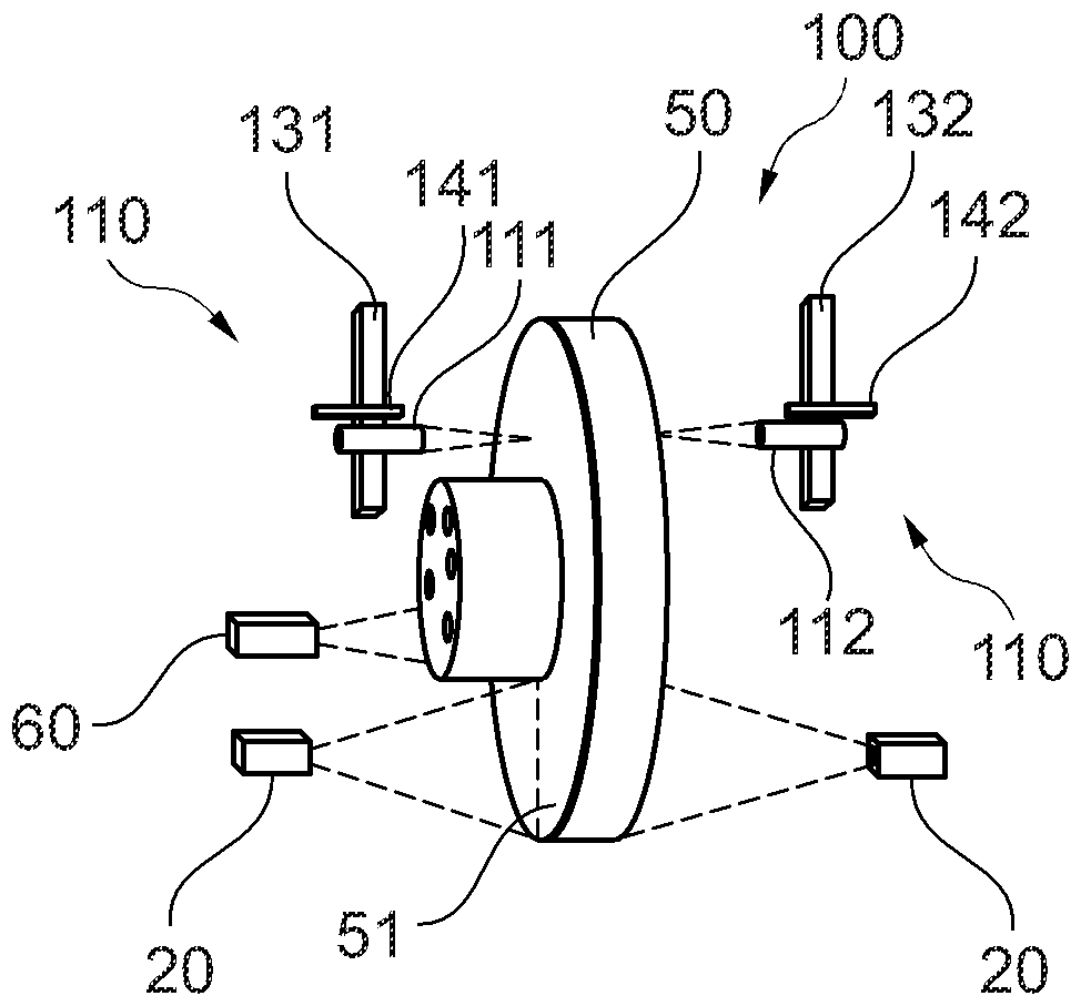
[0044] figure 1 A first embodiment of a sensor device 100 according to the invention is shown. The sensor device according to the invention comprises a first optical sensor system 110 consisting of two parts. Each part of this sensor system 110 is arranged on opposite sides of a disc 50, which may in particular be a brake disc. As already described, the object of the sensor device 100 according to the invention is to determine the layer thickness of the coating of the disc 50 .

[0045] Each subunit of the first optical sensor system 110 comprises an optical sensor 111 , 112 . Each of these sensors 111 , 112 is fastened to a linear guide 131 , 132 and additionally comprises an adjuster 141 , 142 .

[0046] Confocal color sensors that determine the distance from the corresponding side of the disk 50 can be used here as optical sensors 111 , 112 .

[0047] Furthermore, a second optical sensor system 20 is provided, which can be designed, for example, in the form of a line sc...


PUM


Abstract

The invention relates to a sensor device for examining the coating of a disc as part of a coating process. The sensor device comprises a first optical sensor system for determining the layer thicknessof the coating applied to the disc, and comprises a rotation apparatus. The invention is characterized in that the first optical sensor system is designed to simultaneously identify at least one first position-based measured value and one second position-based measured value, the first and the second position-based measured value describing the distance between the sensor systems and the surfaceof the disc. As a result of this, the sensor system is configured such that the first position-based measured value of a coated region of the disc and the second position-based measured value of an uncoated region of the disc are identified. Furthermore, the first optical sensor system comprises at least one linear guide, which extends from the central region to the edge. In addition, a control and analysis apparatus is provided for calculating the layer thickness of the disc at the position of the first position-based measured value with the aid of the first and the second position-based measured value. Furthermore, the invention relates to a coating for a disc, comprising inspecting the coating for determining the layer thickness of the coating applied to the disc.

Description

technical field [0001] The invention relates to a sensor device for inspecting the coating of a disc as part of a coating process, the sensor device comprising a first optical sensor system for determining the layer thickness of the coating applied to the disc and comprising a device for rotating the disc and the invention relates to a coating method for a disc, in particular a brake disc, comprising inspecting the coating to determine the layer thickness of the coating applied to the disc. Background technique [0002] Particulate pollution plays an important role in the current discussion around minimizing air emissions in urban centers, which originate in part from transport. The components PM 10 and PM 2.5 are considered substances harmful to human health and they are of particular relevance here. [0003] Apart from many causes such as combustion processes in power stations or heaters, road traffic also contributes to particle pollution in metropolitan areas. The main...

Claims


Application Information

Patent Timeline
IPC IPC(8): G01B11/06
CPCG01B11/0616G01B11/0683G01B2210/44G01B9/02042G01B11/022B05B12/084B05B12/124B05B13/0221F16D65/127F16D2250/0046G01B11/14G01B11/26G01D5/26
Inventor W·乌尔里希
Owner STURM MASCH & ANLAGENBAU GMBH
Learn More