Supercharge Your Innovation With Domain-Expert AI Agents!

Expansion valve performance automatic detection equipment and process thereof

An automatic detection and expansion valve technology, applied in the direction of mechanical valve testing, etc., can solve problems such as low work efficiency, and achieve the effect of improving efficiency and improving detection efficiency.

Pending Publication Date: 2021-03-02
ZHEJIANG XINJIN AIR CONDITIONING EQUIP
View PDF0 Cites 0 Cited by
  • Summary
  • Abstract
  • Description
  • Claims
  • Application Information

AI Technical Summary

Problems solved by technology

The expansion valve makes the medium-temperature and high-pressure liquid refrigerant become low-temperature and low-pressure wet steam through its throttling, and then the refrigerant absorbs heat in the evaporator to achieve the cooling effect. The expansion valve controls the flow rate of the valve through the change of the superheat at the end of the evaporator to prevent Insufficient utilization of the evaporator area and cylinder knocking phenomenon. After the expansion valve is produced, the performance of the expansion valve needs to be tested. Generally, the performance is tested by connecting the expansion valve to the refrigerant pipe of the refrigeration system and detecting the refrigerant throughput at different temperatures. , but most of the existing detection equipment for expansion valves are installed manually, and the work efficiency is low. Therefore, we propose an automatic detection equipment for expansion valve performance and its process

Method used


Image

  • Expansion valve performance automatic detection equipment and process thereof
  • Expansion valve performance automatic detection equipment and process thereof
  • Expansion valve performance automatic detection equipment and process thereof

Examples


Embodiment Construction

[0022] The following will clearly and completely describe the technical solutions in the embodiments of the present invention with reference to the accompanying drawings in the embodiments of the present invention. Obviously, the described embodiments are only some, not all, embodiments of the present invention. Based on the embodiments of the present invention, all other embodiments obtained by persons of ordinary skill in the art without making creative efforts belong to the protection scope of the present invention.

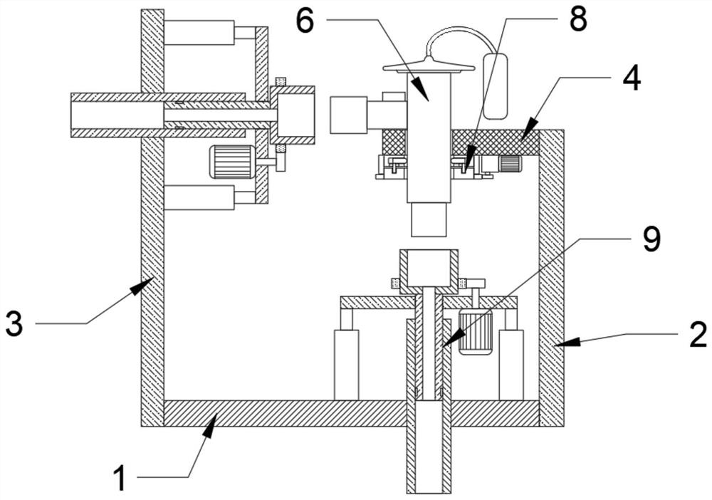
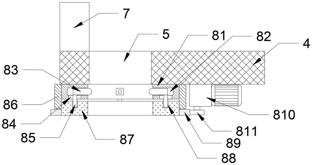
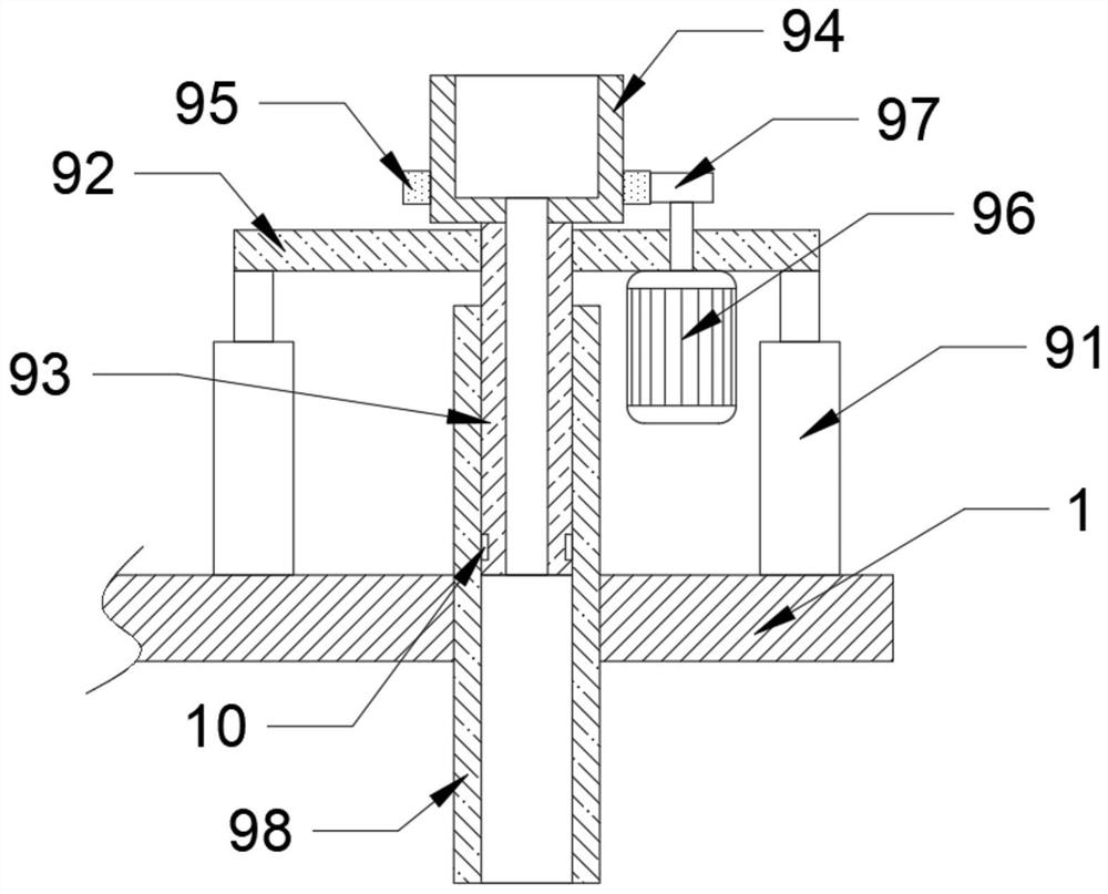
[0023] see figure 1 and figure 2 , a kind of expansion valve performance automatic detection equipment in the figure, including a bottom plate 1 and an expansion valve body 6, a first vertical plate 2 is fixed at one end of the bottom plate 1, and a The second vertical plate 3, the top side of the first vertical plate 2 is fixed with an L-shaped mounting plate 4, and one end of the L-shaped mounting plate 4 is provided with a mounting hole 5, and the inner w...


PUM


Abstract

The invention discloses expansion valve performance automatic detection equipment comprising a bottom plate and an expansion valve body; a first vertical plate is fixed to one end of the bottom plate,a second vertical plate is fixed to the end, away from the first vertical plate, of the bottom plate, an L-shaped mounting plate is fixed to one side of the top of the first vertical plate, and a mounting hole is formed in one end of the L-shaped mounting plate; an expansion valve body is inserted into the inner wall of the mounting hole, a clamping groove is formed in the end, away from the first vertical plate, of the L-shaped mounting plate, a liquid outlet end of the expansion valve body is connected with the clamping groove in a clamped mode, and a clamping mechanism is fixed to the end,close to the mounting hole, of the bottom of the L-shaped mounting plate. According to the invention, the expansion valve body is inserted into the L-shaped mounting plate; the expansion valve body is clamped and fixed through the clamping mechanism, and the expansion valve body is connected with a fixed pipe through a joint mechanism, so that the expansion valve body is connected in a refrigeration system, and the expansion valve body is detected, so that the efficiency of installing the expansion valve body by people is improved, and the detection efficiency is further improved.

Description

technical field [0001] The invention relates to the technical field of expansion valve performance detection, in particular to an expansion valve performance automatic detection device and a process thereof. Background technique [0002] The expansion valve is an important part in the refrigeration system, generally installed between the liquid storage cylinder and the evaporator. The expansion valve makes the medium-temperature and high-pressure liquid refrigerant become low-temperature and low-pressure wet steam through its throttling, and then the refrigerant absorbs heat in the evaporator to achieve the cooling effect. The expansion valve controls the flow rate of the valve through the change of the superheat at the end of the evaporator to prevent Insufficient utilization of the evaporator area and cylinder knocking phenomenon. After the expansion valve is produced, the performance of the expansion valve needs to be tested. Generally, the performance is tested by connec...

Claims


Application Information

Patent Timeline
Patent Type & Authority Applications(China)
IPC IPC(8): G01M13/003
CPCG01M13/003
Inventor 金霞霞范爱松范海燕叶南伟
Owner ZHEJIANG XINJIN AIR CONDITIONING EQUIP
Features
  • R&D
  • Intellectual Property
  • Life Sciences
  • Materials
  • Tech Scout
  • Unparalleled Data Quality
  • Higher Quality Content
  • 60% Fewer Hallucinations
Learn More