Precision optical machine assembly method of trapezoidal prism optical system

A trapezoidal prism and optical system technology, applied in optics, optical components, installation, etc., can solve the problems of low assembly accuracy, unable to meet the high-precision assembly requirements of the trapezoidal prism optical path, etc., and achieve the effect of high-precision reference conversion

Active Publication Date: 2021-03-02
XI'AN INST OF OPTICS & FINE MECHANICS - CHINESE ACAD OF SCI
View PDF11 Cites 5 Cited by
  • Summary
  • Abstract
  • Description
  • Claims
  • Application Information

AI Technical Summary

Problems solved by technology

[0004] In order to solve the technical problem that the existing mechanical assembly accuracy is low and cannot meet the high-precision assembly requirements of

Method used


Image

  • Precision optical machine assembly method of trapezoidal prism optical system
  • Precision optical machine assembly method of trapezoidal prism optical system
  • Precision optical machine assembly method of trapezoidal prism optical system

Examples


Embodiment 1

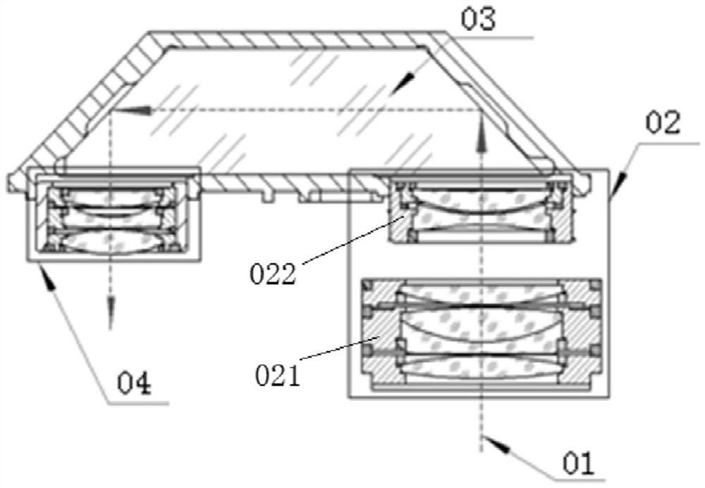
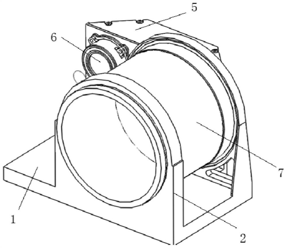
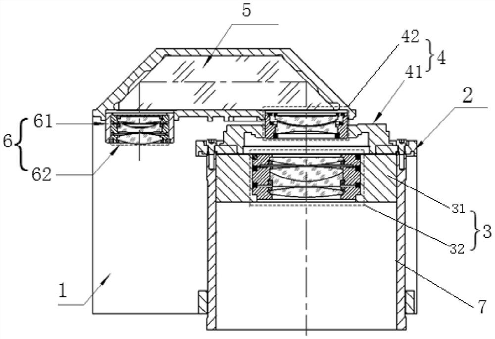
[0091] like figure 2 and image 3 As shown, a trapezoidal prism optical system includes a base plate 1, a bracket 2, a long barrel 7, a first front-end optical assembly 3, a second front-end optical assembly 4, a trapezoidal prism 5, and a rear-end optical assembly 6; the first front-end optical assembly Assembly 3 includes a first lens barrel 31 and a first front lens group 32, a second front optical assembly 4 includes a second lens barrel 41 and a second front lens group 42, and a rear optical assembly 6 includes a third lens barrel 61 and a rear Optical lens group 62, the long lens barrel 7 is installed on the bracket 2 by screws, the first lens barrel 31 is assembled inside the long lens barrel 7; the second lens barrel 41 is installed on the bracket 2; the bottom plate 1 provides bottom mounting for all structures benchmark. In this embodiment, the cooperation between the first front-end lens group 32 and the first lens barrel 31, between the second front-end lens gro...

Embodiment 2

[0123] The difference from Embodiment 1 is that before the trapezoidal prism optical system is assembled, the first front end lens group 32 is not installed on the first lens barrel 31, the second front end lens group 42 is not installed on the second lens barrel 41, and the rear end lens group 42 is not installed on the second lens barrel 41. The third lens barrel 61 is not installed in the optical lens group 62, then the precision optomechanical assembly method of the trapezoidal prism optical system:

[0124] In step 1.2), before the first tool reticle 81 is loaded into the first lens barrel 31, the first front-end lens group 32 does not need to be removed;

[0125] In step 2.2), before the second tooling reticle 82 is loaded into the second lens barrel 41, it is not necessary to dismantle the second front end lens group 42;

[0126] In step 5.3), before the third tool reticle 83 is loaded into the third lens barrel 61 , the rear optical lens group 62 does not need to be di...


PUM


Abstract

The invention provides a precision optical machine assembly method of a trapezoidal prism optical system, and solves problems that existing mechanical assembly precision is low, and the high-precisionassembly requirement of a trapezoidal prism optical path cannot be met. The method comprises the following steps: 1) installing a first tool cross wire in a first lens cone, and taking an optical axis of a small circle in the center of the first tool cross wire as a main reference for assembly; 2) adjusting the mounting posture of a second lens cone on a bracket by using an auto-collimation theodolite; 3) moving the auto-collimation theodolite to an emergent light path of a trapezoidal prism, and adjusting the posture of the auto-collimation theodolite; 4) assembling a first front-end lens group into the first lens cone, and assembling a second front-end lens group into the second lens cone; 5) adjusting the translation amount of the trapezoidal prism on the bottom plate and a gasket between the third lens cone and the trapezoidal prism till that an auto-collimation image and the central cross wire image of the third tool cross wire on the third lens cone are aligned with the center of the eyepiece of the auto-collimation theodolite; and 6) assembling a rear-end optical lens group into the third lens cone.

Description

technical field [0001] The invention belongs to the field of precision optical mechanical assembly, and relates to a trapezoidal prism assembly technology, in particular to a precision optical-mechanical assembly method of a trapezoidal prism optical system. Background technique [0002] Trapezoidal prism refracting the optical path is a typical optical structure, and its purpose is to refract the optical path multiple times and reduce the overall size of the optical-mechanical system. Compared with non-refracting optical systems, trapezoidal prism refracting optical path has higher requirements for optical machine assembly. [0003] like figure 1 As shown, a typical trapezoidal prism optical system, the incident light 01 first passes through the front-end optical system 02, is reflected twice by the trapezoidal prism 03, and then exits through the rear-end optical system 04. The first front-end optical assembly 021 and the second front-end optical assembly 022. In order ...

Claims


Application Information

Patent Timeline
IPC IPC(8): G02B7/18G02B27/62
CPCG02B7/1805G02B27/62
Inventor 雷昱康世发秦星何磊李硕
Owner XI'AN INST OF OPTICS & FINE MECHANICS - CHINESE ACAD OF SCI
Why Eureka
Try Eureka