Electromagnet control switch electromagnet thrust direction action structure

A technology to control the direction of switch and thrust, applied in the direction of protection switch operation/release mechanism, etc., can solve the problems of high pressure in one-sided interrupter, complex structure of segmented mechanism, shortened service life of contacts, etc., and achieve enhanced action accuracy , The effect of small force loss and simple structure

Pending Publication Date: 2021-03-02
浙江新控电气科技有限公司
View PDF0 Cites 0 Cited by
  • Summary
  • Abstract
  • Description
  • Claims
  • Application Information

AI Technical Summary

Problems solved by technology

[0002] At present, the breaking mechanism of the control and protection switching appliances provided on the market generally includes a base and a cover plate. The base is movable with a contact support passing through the cover plate. The contact support is provided with an electromagnetic pressure plate. Iron core, static iron core and other structures can swing, and then drive the contact support to move up and down. This segmented mechanism has a complex structure, takes up a large space, and has high cost. Moreover, the swing of the electromagnetic pressure plate drives the contact support to move up and down, which is easy to cause burning phenomenon. , thereby shortening the service life of the contacts in the base, and may also cause excessive pressure in the unilateral arc extinguishing chamber in the base

Method used


Image

  • Electromagnet control switch electromagnet thrust direction action structure
  • Electromagnet control switch electromagnet thrust direction action structure
  • Electromagnet control switch electromagnet thrust direction action structure

Examples


Embodiment Construction

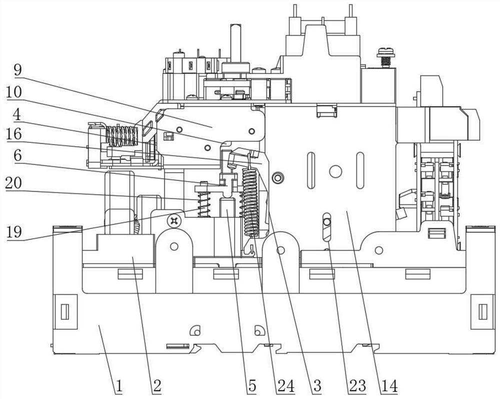
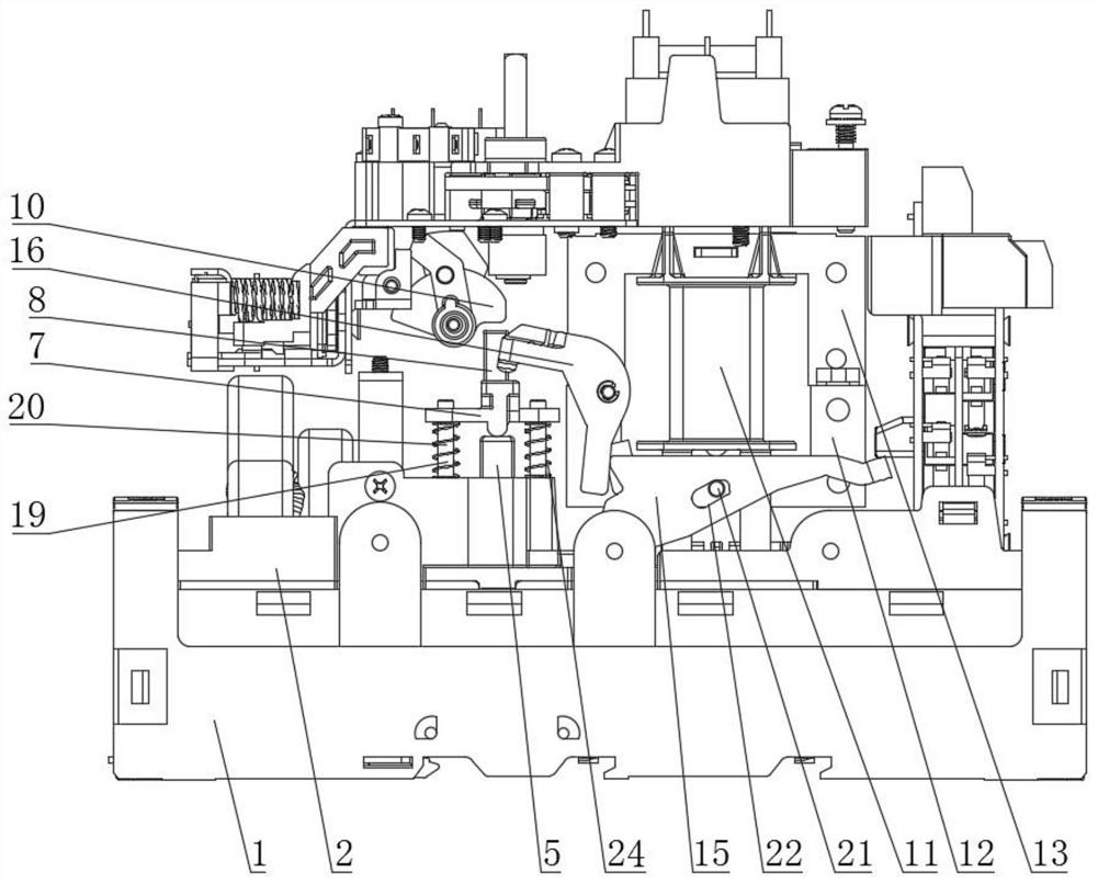
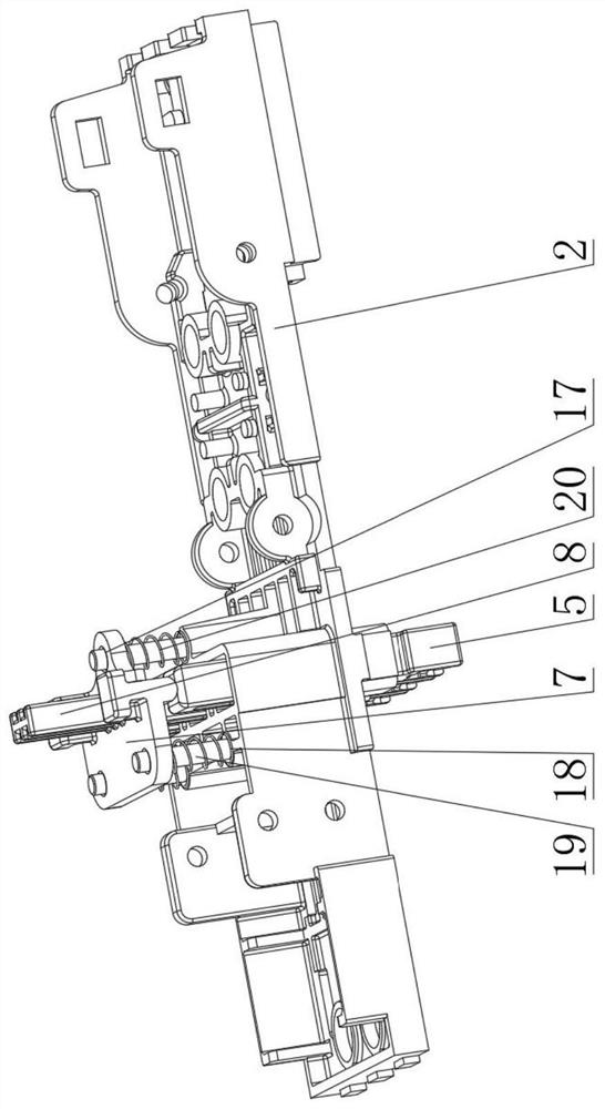
[0018] As shown in the accompanying drawings, an electromagnet control switch electromagnet thrust direction action structure provided by the present invention includes a base 1 and a cover plate 2, and the cover plate 2 is provided with an electromagnetic mechanism 3 and an operating mechanism 4. The base 1 is equipped with a contact support 5 passing through the cover plate 2, and an electromagnetic pressure plate 6 is provided on the contact support 5. It is characterized in that: the electromagnetic pressure plate 6 is linked with the electromagnetic mechanism 3 and the operating mechanism 4 to drive the contact support. 5 moves up and down, the electromagnetic pressure plate 6 includes a flat plate 7 and a column 8 arranged on the flat plate 7, the operating mechanism 4 includes a housing 9 and a transmission cam 10 hinged on the housing 9, and the projections of the transmission cam 10 are The upper end of the quasi-column 8, the electromagnetic mechanism 3 includes a bob...


PUM


Abstract

The invention discloses an electromagnet control switch electromagnet thrust direction action structure which comprises a base and a cover plate, an electromagnetic mechanism and an operating mechanism are arranged on the cover plate, a contact support penetrating out of the cover plate is movably arranged in the base, and an electromagnetic pressing plate is arranged on the contact support. The structure is characterized in that the electromagnetic pressing plate is linked with the electromagnetic mechanism and the operating mechanism to drive the contact support to move up and down. The electromagnet thrust direction action structure of the electromagnet control switch can be linked with an electromagnetic mechanism and an operating mechanism, the structure is simpler, more space is saved, the cost is lower, and the contact support action accuracy can be ensured.

Description

technical field [0001] The invention relates to the field of low-voltage electrical appliances, in particular to an electromagnet control switch electromagnet thrust direction action structure. Background technique [0002] At present, the breaking mechanism of the control and protection switching appliances provided on the market generally includes a base and a cover plate. The base is movable with a contact support passing through the cover plate. The contact support is provided with an electromagnetic pressure plate. Iron core, static iron core and other structures can swing, and then drive the contact support to move up and down. This segmented mechanism has a complex structure, takes up a large space, and has high cost. Moreover, the swing of the electromagnetic pressure plate drives the contact support to move up and down, which is easy to cause burning phenomenon. , thereby shortening the service life of the contacts in the base, and may also cause excessive pressure ...

Claims


Application Information

Patent Timeline
Patent Type & Authority Applications(China)
IPC IPC(8): H01H71/24
CPCH01H71/24
Inventor 刘超儒穆茂林
Owner 浙江新控电气科技有限公司
Why Eureka
Try Eureka