Optical fiber communication equipment signal monitoring device

A technology of signal monitoring and optical fiber communication, which is applied in the direction of optical fiber transmission, transmission monitoring/testing/fault measurement system, etc. It can solve the problems of labor overdraft, affecting the appearance, single function, etc., and achieve the effect of convenient use, easy storage and protection

Active Publication Date: 2021-03-02
武汉鑫炀科技发展有限责任公司
View PDF9 Cites 0 Cited by
  • Summary
  • Abstract
  • Description
  • Claims
  • Application Information

AI Technical Summary

Problems solved by technology

[0002] The service life of fiber optic cables is much longer than that of traditional copper cables, and the cost and maintenance costs of fiber optic cables are much lower than that of copper cables. Therefore, optical fiber network technology that uses fiber optic cables as the signal transmission medium In order to become the communication method developed by broadband operators today, optical fiber communication equipment needs to be connected to the basic equipment at the end of the optical fiber network through the optical fiber cable it is equipped with, and the optical fiber network is laid to the user end to achieve fiber-to-the-home The goal is to add a cable reel to the chassis or upper cover of the optical fiber communication equipment for winding redundant optical fiber cables after laying, so as to avoid irregular winding of optical fiber cables and affect the appearance, and to avoid optical fiber Due to the excessively large bending radius of the cable, the signal transmission energy is attenuated or even damaged. It is necessary to monitor the signal during use, so as to quickly find the strength of the signal. In addition, the existing equipment can only be used by hand. Causes labor overdraft, cannot be used for fixed support, and has a single function

Method used


Image

  • Optical fiber communication equipment signal monitoring device
  • Optical fiber communication equipment signal monitoring device
  • Optical fiber communication equipment signal monitoring device

Examples


Embodiment approach

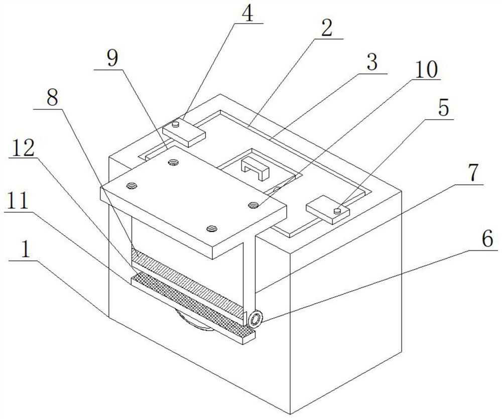
[0027] As a preferred embodiment of the present invention, a limiting plate 11 is welded on the rotating disk 14 , and a powerful magnet 2 12 is installed on the limiting plate 11 , and the powerful magnet 2 12 cooperates with the powerful magnet 1 8 .

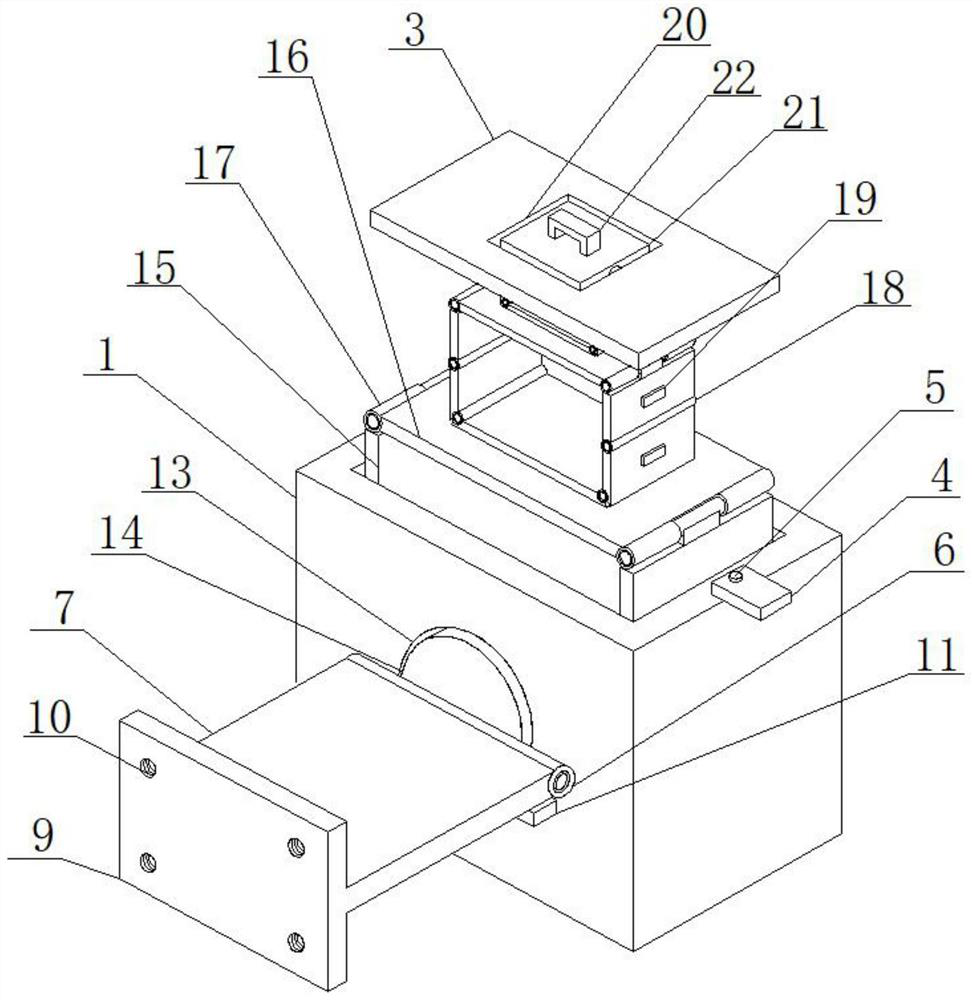
[0028] As a preferred embodiment of the present invention, a load-bearing plate 16 is installed inside the box body 1, and a support plate 15 is installed on the load-bearing plate 16, and the support plate 15 is installed on the load-bearing plate 16 through a fixed shaft one 17. superior.

[0029] As a preferred embodiment of the present invention, the support plates 15 are connected by a second fixed shaft 18 , and magnets 19 are mounted on the support plates 15 .

[0030] As a preferred embodiment of the present invention, the first fixed shaft 17 and the second fixed shaft 18 both include an outer rod 28 and an inner rod 26 , and a torsion spring 27 is installed between the outer rod 28 and the inner rod 26 .

[0031] As...


PUM


Abstract

The invention provides an optical fiber communication equipment signal monitoring device which comprises a monitoring device body, the monitoring device body comprises a box body, an opening is formedin the top of the box body, a box cover is installed in the opening, a fixing plate is installed on the box body, and the fixing plate is installed on the box body through a rotating shaft. The optical fiber communication equipment signal monitoring device comprises a box cover, a fixed plate is arranged on the box cover, the fixed plate is matched with the box cover, an open groove is formed inthe box cover, a movable plate is installed in the open groove through a rotating rod, a handle is installed at the top of the movable plate, and when the optical fiber communication equipment signalmonitoring device is used, a connecting plate can be opened and fixed through a strong magnet. The connecting plate forms a workbench to be used, a computer is placed on the connecting plate to be used, in addition, when signals need to be searched for and used, the bottom plate makes contact with the ground and is fixed, the rotating disc rotates, and therefore the signals at different positionscan be rapidly monitored and used.

Description

technical field [0001] The invention relates to the field of signal monitoring equipment for optical fiber communication equipment, in particular to a signal monitoring device for optical fiber communication equipment. Background technique [0002] The service life of fiber optic cables is much longer than that of traditional copper cables, and the cost and maintenance costs of fiber optic cables are much lower than that of copper cables. Therefore, optical fiber network technology that uses fiber optic cables as the signal transmission medium In order to become the communication method developed by broadband operators today, optical fiber communication equipment needs to be connected to the basic equipment at the end of the optical fiber network through the optical fiber cable it is equipped with, and the optical fiber network is laid to the user end to achieve fiber-to-the-home The goal is to add a cable reel to the chassis or upper cover of the optical fiber communication...

Claims


Application Information

Patent Timeline
Patent Type & Authority Applications(China)
IPC IPC(8): H04B10/07H04B10/25
CPCH04B10/07H04B10/25
Inventor 江立皇甫鹏崔艳玲
Owner 武汉鑫炀科技发展有限责任公司
Why Eureka
Try Eureka