Self-propelled pest control machine

A self-propelled, plant protection technology, applied in mechanical equipment, lighting and heating equipment, lighting devices, etc., can solve problems such as undocumented energy storage configuration structure, and achieve the effect of reduced impact and good balance

Pending Publication Date: 2021-03-05
ISEKI & CO LTD
View PDF1 Cites 0 Cited by
  • Summary
  • Abstract
  • Description
  • Claims
  • Application Information

AI Technical Summary

Problems solved by technology

[0002] As described in Patent Document 1, self-propelled plant protection machinery lifts and deploys the spraying boom through hydraulic control. energy device, but Patent Document 1 does not describe the arrangement structure of the energy storage device to the body

Method used


Image

  • Self-propelled pest control machine
  • Self-propelled pest control machine
  • Self-propelled pest control machine

Examples


Embodiment Construction

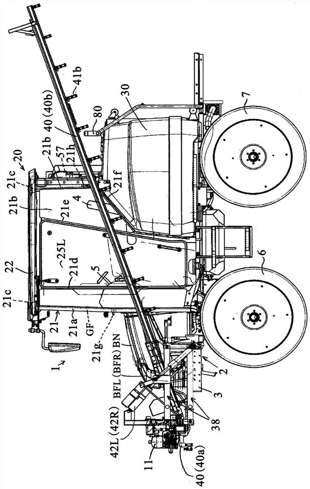
[0028] Hereinafter, embodiments of the present invention will be described with reference to examples shown in the drawings. In addition, in the description of the embodiment, toward the forward direction of the body, the left and right directions are respectively referred to as left and right, the forward direction is referred to as front, and the backward direction is referred to as rear, but this does not limit the structure of the present invention.

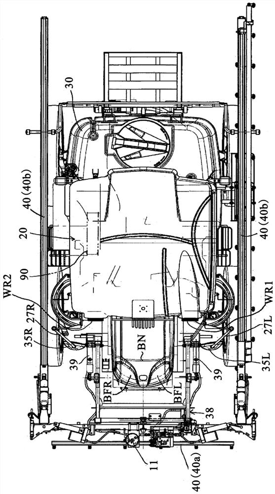
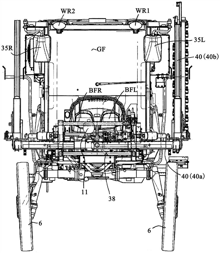
[0029] The self-propelled plant protection machine 1 of the present embodiment is a work vehicle in which an operator such as an operator rides on the traveling body 2 for driving operation, and spreads chemical agents on farmland. Such as Figure 1 ~ Figure 3 As shown, the self-propelled plant protection machine 1 includes a traveling body 2 , a driver's cab 20 , a chemical agent box 30 , and a plant protection spray bar 40 for spreading the chemical agent supplied from the chemical agent box 30 to farmland, and the like.

...


PUM


Abstract

The present invention addresses the problem of providing a self-propelled plant protection machine which is used by laterally extending spreading spray rods disposed on the left and right sides of a machine body, and which has good travel stability by disposing an energy storage device provided in a hydraulic drive circuit for driving a lift cylinder for lifting the spray rods in a balanced manneron a travel vehicle body. A pesticide box (30) is mounted on the rear side of a main frame (3) equipped with left and right front wheels (6) and rear wheels (7), a spray rod frame (38) equipped witha plant protection spray rod(40) is mounted on the front side, and a central spray rod (40a) and left and right side spray rods (40b) are mounted on the spray rod frame (38) in a liftable manner. Thefront part of the machine body is provided with a lifting energy storage device (11) for buffering the pressure change of a lifting cylinder barrel (39) for lifting the spray rod frame (38).

Description

technical field [0001] The present invention relates to a self-propelled plant protection machine (boom sprayer) which deploys a sowing spray bar on the left and right sides of the machine body and carries out plant protection work while driving. Background technique [0002] As described in Patent Document 1, self-propelled plant protection machinery lifts and deploys the spraying boom through hydraulic control. Accumulator, but Patent Document 1 does not describe the disposition structure of this accumulator to the body. [0003] prior art literature [0004] patent documents [0005] Patent Document 1: Japanese Patent Laid-Open No. 2017-184695 Contents of the invention [0006] The problem to be solved by the invention [0007] Since the accumulator is heavy, it is necessary to consider the mounting position for maintenance and inspection. In addition, the weight balance of the traveling body needs to be considered. [0008] The object of the present invention is ...

Claims


Application Information

Patent Timeline
Patent Type & Authority Applications(China)
IPC IPC(8): A01M7/00A01C23/04F16F15/023
CPCA01M7/0014A01M7/0082A01M7/0071A01C23/047F16F15/023A01M7/0042A01M7/0053A01M7/005A01M7/0085F21V33/00A01M2200/01
Inventor 长尾康史长谷喜八郎
Owner ISEKI & CO LTD
Why Eureka
Try Eureka