Dust removal device for building construction

A dust removal device and construction technology, applied in the direction of transportation and packaging, separation of dispersed particles, chemical instruments and methods, etc., can solve problems such as blockage, limitation of the contact surface between air and filter, and affect filtration efficiency, so as to improve filtration efficiency, High filtering effect, the effect of increasing the chance of contact

Inactive Publication Date: 2021-03-05
张治发
View PDF0 Cites 4 Cited by
  • Summary
  • Abstract
  • Description
  • Claims
  • Application Information

AI Technical Summary

Problems solved by technology

[0003] In the construction process, it needs to be treated. When the air is filtered in the prior art, the air flow direction of the filter is usually perpendicular to the filter, so that the contact surface between the air and the filter is limited. At the same time, the particles in the air and the filter cylinder Vertical collision, it is easy to be fixed and stuck on the filter net, causing partial blockage and affecting the filtration efficiency; therefore, a dust removal device for construction is now provided to solve this technical problem

Method used


Image

  • Dust removal device for building construction
  • Dust removal device for building construction
  • Dust removal device for building construction

Examples


Embodiment 1

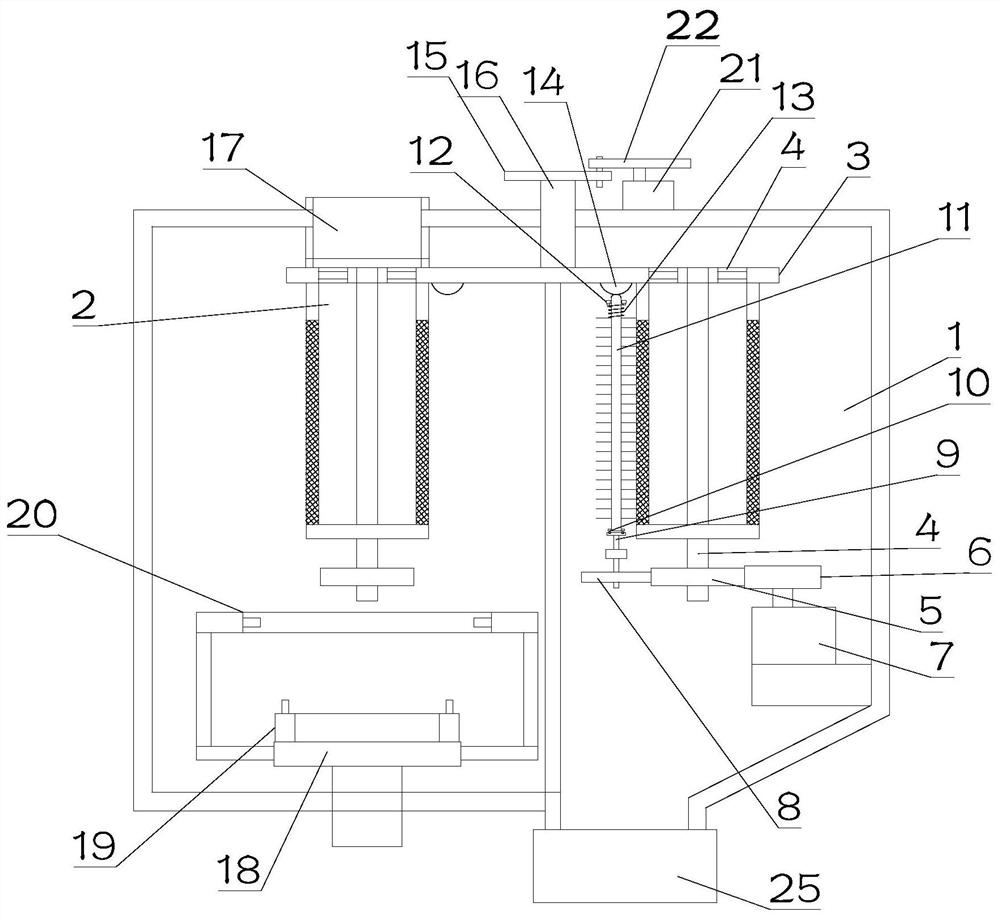
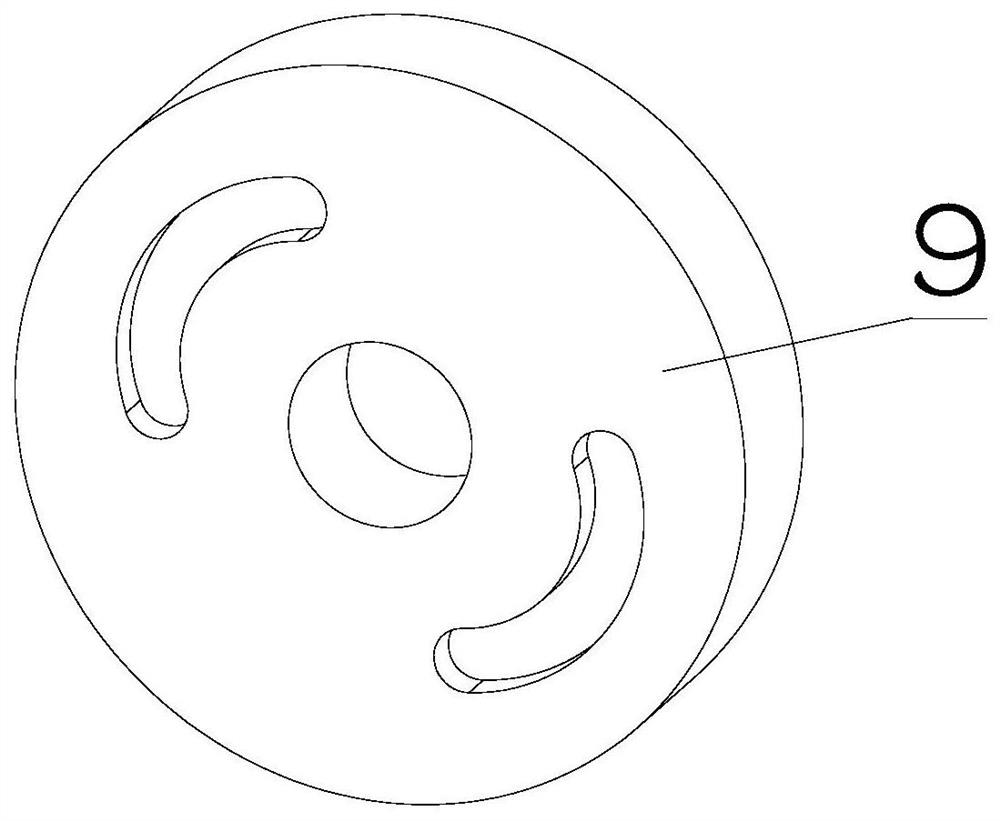
[0023] see Figure 1~3 , in Embodiment 1 of the present invention, a structure diagram of a dust removal device for building construction provided by the embodiment of the present invention, including: a device main body 1, the interior is divided into a dust removal chamber and a cleaning chamber by a partition; the interior of the device main body 1 Intermittent rotation is provided with a rotating disc 3, the bottom of the rotating disc 3 is provided with a plurality of filter cylinders 2 in an array, and the lower ends of the plurality of filter cylinders 2 are fixedly sleeved on the outside of the supporting shaft 26, and the upper end of the supporting shaft 26 is rotatably mounted on the rotating shaft. On the disc 3, a plurality of through holes 4 are arranged in an array on the rotating disc 3, and the plurality of through holes 4 are arranged one by one at the outlet above the plurality of filter screen cylinders 2; the inside of the dust removal chamber is also provi...

Embodiment 2

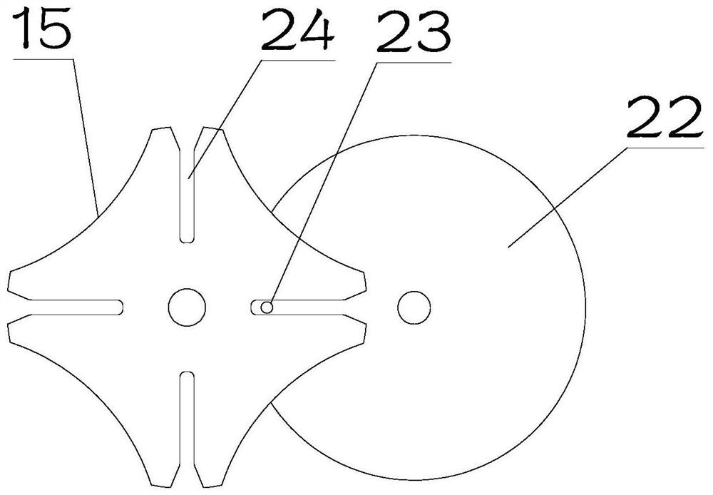
[0026] see Figure 1~3 The main difference between this embodiment 2 and embodiment 1 is that in order to be able to clean the filter screen cylinder 2 inside the cleaning chamber, a brush 11 is provided for self-rotation inside the cleaning chamber, and the brush 11 is attached to the cleaning chamber. On the surface of one of the filter screen cylinders 2 inside, a driving assembly is provided inside the cleaning chamber for driving the filter screen cylinder 2 to rotate.

[0027] Specifically, the drive assembly includes a self-rotating driving disk 6, which is frictionally set with the transmission disk 5 at the bottom of the supporting shaft 26, and the driving disk 6 and the transmission disk 5 are both rubber wheels, so that the supporting shaft When the drive disc 5 on the 26 was close to the drive disc 6, the drive disc 6 could drive the drive disc 5 to drive the supporting rotating shaft 26 to rotate, so as to provide power for the drive disc 5 to rotate.

[0028] T...


PUM


Abstract

The invention is suitable for the technical field of building construction equipment, and provides a dust removal device for building construction. The device includes a device main body, and the interior of the device main body is divided into a dust removal cavity and a cleaning cavity by a partition plate; a rotating disc is arranged in the device main body in an intermittent rotating mode, a plurality of filter screen cylinders are arranged at the bottom of the rotating disc in an array mode, the outer sides of supporting rotating shafts are fixedly sleeved with the lower ends of the multiple filter screen cylinders, and the upper ends of through holes are rotationally installed on the rotating disc, wherein the rotating disc is provided with multiple through holes in an array mode, and the multiples through holes are formed in outlets at the upper parts of the plurality of filter screen cylinders in a one-to-one correspondence manner; an exhaust cylinder is further arranged in thedust removal cavity, and the lower portion of the exhaust cylinder is arranged on one through hole in the dust removal cavity; an air inlet piece is fixedly mounted in the dust removal cavity, and isarranged below one filter screen cylinder of which the upper end communicates with the exhaust cylinder; and a plurality of first spray heads with upward openings are arranged on the air inlet piecein a circumferential array mode.

Description

technical field [0001] The invention relates to the technical field of building construction equipment, in particular to a dust removal device for building construction. Background technique [0002] Building construction refers to the production activities in the implementation stage of engineering construction. It is the construction process of various buildings. It can also be said to be the process of turning various lines on the design drawings into real objects at designated locations. [0003] In the construction process, it needs to be treated. When the air is filtered in the prior art, the air flow direction of the filter is usually perpendicular to the filter, so that the contact surface between the air and the filter is limited. At the same time, the particles in the air and the filter cylinder Vertical collision, it is easy to be fixed and stuck on the filter screen, causing partial blockage and affecting the filtration efficiency; therefore, a dust removal devic...

Claims


Application Information

Patent Timeline
Patent Type & Authority Applications(China)
IPC IPC(8): B01D46/24B01D46/00
CPCB01D46/2411B01D46/66
Inventor 张治发
Owner 张治发
Why Eureka
Try Eureka