
High-temperature-resistant, safe and explosion-proof quick-opening blind plate structure

A high temperature resistant and explosion-proof technology, used in safety valves, functional valve types, lift valves, etc., can solve problems such as nowhere to release pressure, equipment safety hazards, damage to sealing rings, etc., to prevent leakage, improve safety, The effect of improving the service life

Pending Publication Date: 2021-03-05
天津盒星环保科技有限公司
View PDF0 Cites 1 Cited by
  • Summary
  • Abstract
  • Description
  • Claims
  • Application Information

AI Technical Summary

Problems solved by technology

[0004] The existing quick-opening blind plate is limited by the material of the sealing ring, and the operating temperature is generally between -20°C and 90°C; when the pressure pipe or pressure vessel encounters an extreme situation-the pressure suddenly rises or even explodes, the pressure has no place to release, and the equipment will be damaged. security risks;
[0005] When the existing quick-opening blind plate is sealed, the blind plate and the sealing ring will move relative to each other, which will easily cause damage to the sealing ring and cause leakage

Method used


Image

  • High-temperature-resistant, safe and explosion-proof quick-opening blind plate structure
  • High-temperature-resistant, safe and explosion-proof quick-opening blind plate structure

Examples


Embodiment 1

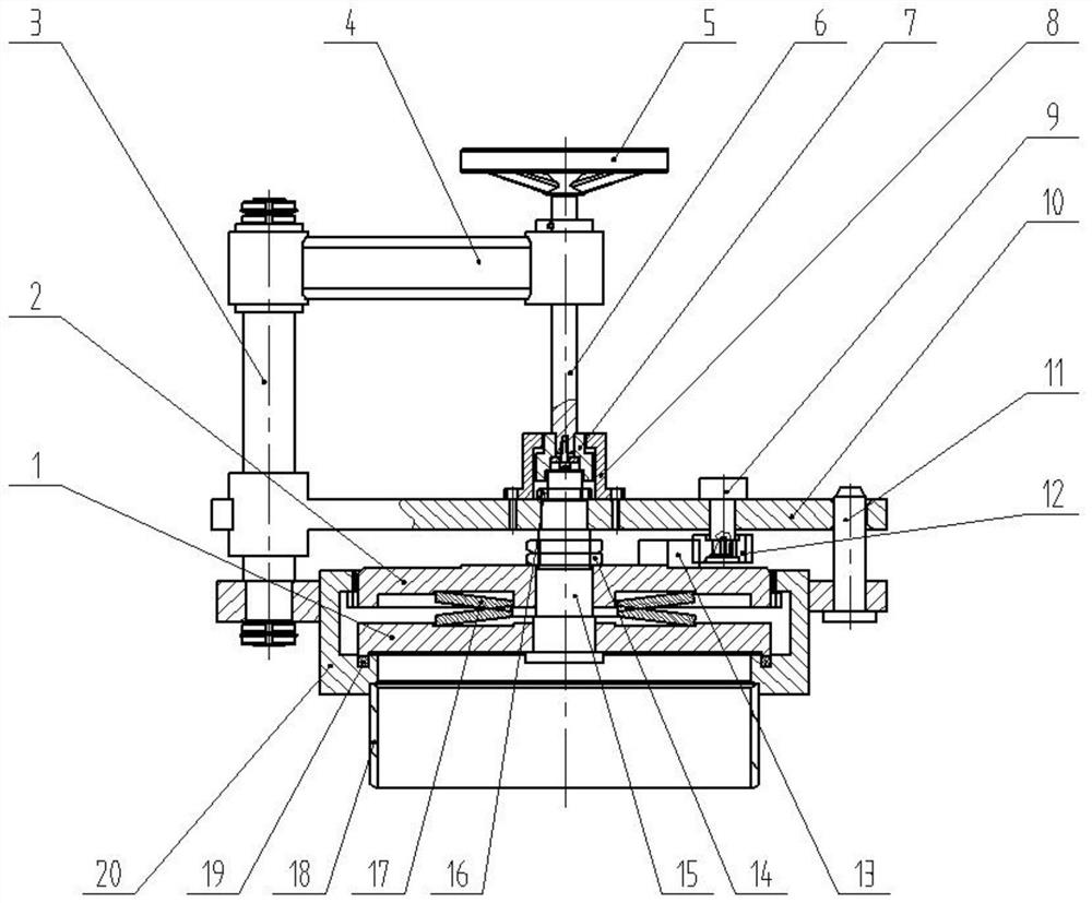
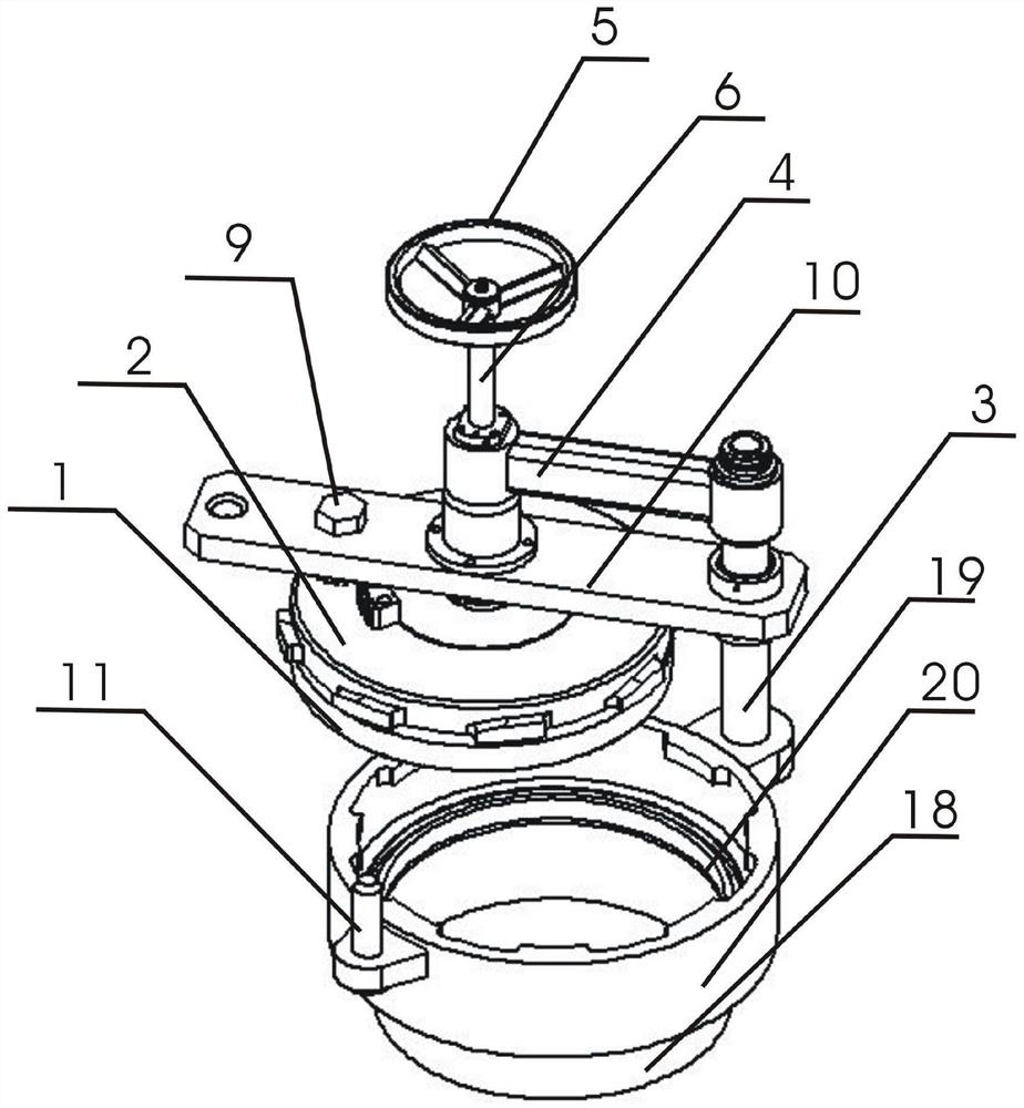
[0024] The invention provides a high-temperature-resistant, safe and explosion-proof quick-opening blind plate structure, including a quick-opening blind plate body 1, a gland 2, a rotating shaft 3, a rotating arm 4, a handwheel 5, a lead screw 6, a connector 7, and an end cover 8. Gear shaft 9, positioning plate 10, guide shaft 11, pinion 12, large gear 13, large lock nut 14, mandrel 15, disc spring 17, cylinder 18, graphite sealing ring 19, cylinder seat 20, hand The lower side of the wheel 5 is connected with the lead screw 6, the lead screw 6 is set on one end of the shaft arm, the other end of the shaft arm is set on the rotating shaft 3, the lower side of the rotating shaft 3 passes through the installation groove on the side of the cylinder seat 20 and is fixed by a nut, The lower end of the lead screw 6 is connected to the connector 7, the connector 7 is installed inside the end cover 8, the end cover 8 is fixed on the positioning plate 10 by bolts, one end of the posit...

Embodiment 2

[0026] When the quick opening blind plate needs to be closed, turn the hand wheel 5, the hand wheel 5 drives the screw 6 to rotate downward, and the positioning plate 10, the gland 2, and the quick opening blind plate 1 move downward along the rotating shaft 3 through the connector 7 , until the positioning hole of the positioning plate 10 penetrates the guide shaft 11, the quick opening blind plate body 1 is pressed against the graphite sealing ring 19, stop turning the handwheel 5 at this time, and then use a torque wrench to turn the gear shaft 9, the gear shaft 9 drives the small The gear 12 rotates, so that the small gear 12 drives the large gear 13 and the gland 2 to rotate around the mandrel 15 together. At this time, the inclined surface of the boss of the outer ring of the gland 2 and the cylinder seat 20 generate axial thrust along the boss, and the disc spring 17 Push the quick-opening blind plate body 1 to compress the graphite sealing ring 19 in the axial direction...

Embodiment 3

[0028] When opening the quick-opening blind plate: first turn the gear shaft 9 with a torque wrench, so that the small gear 12 drives the large gear 13 and the gland 2 to rotate around the mandrel 15 until the boss of the outer ring of the gland 2 and the upper edge of the cylinder seat 20 The bosses are completely staggered. At this time, turn the hand wheel 5 to drive the screw 6 and move the positioning plate 10, the gland 2, and the quick-opening blind plate 1 upwards along the rotating shaft 3 through the connector 7. When moving to the bottom plane of the quick-opening blind plate 1 When it is higher than the upper plane of the cylinder seat 20, the rotating arm 4 can be rotated along the rotating shaft 3, so that the quick-opening blind plate 1 can be opened to a suitable position such as figure 2 .


PUM


Abstract

The invention provides a high-temperature-resistant, safe and explosion-proof quick-opening blind plate structure. The high-temperature-resistant, safe and explosion-proof quick-opening blind plate structure is characterized by comprising a quick-opening blind plate body, a gland, a rotating shaft and the like; the lower side of a hand wheel is connected with a lead screw; the lead screw is arranged at one end of a shaft arm in a sleeving mode; the other end of the shaft arm is arranged on the rotating shaft in a sleeving mode; the lower side of the rotating shaft penetrates through a mountinggroove in the side face of a cylinder body and is fixed through a nut; and the lower end of the lead screw is connected with a connecting head. According to the high-temperature-resistant, safe and explosion-proof quick-opening blind plate structure, the quick-opening blind plate body and the gland are of a coaxial double-plate structure; when the gland is rotated, the outer ring boss inclined face of the gland and the upper edge boss of a cylinder seat generate axial thrust; a quick-opening blind plate is pushed to move horizontally to press a graphite sealing ring; and due to the fact thatthe quick-opening blind plate is fixedly connected with a positioning plate, friction between the quick-opening blind plate and the graphite sealing ring is avoided under the action of a guide shaft and the rotating shaft, so that leakage caused by damage of the graphite sealing ring is prevented, and the service life of the graphite sealing ring is prolonged.

Description

technical field [0001] The invention relates to the technical field of quick-opening blind plates for pyrolysis furnaces, in particular to a high-temperature-resistant, safe and explosion-proof quick-opening blind plate structure. Background technique [0002] The quick opening blind plate is a mechanical device used on the circular opening of the pressure pipe or pressure vessel, and can realize quick opening or closing. [0003] The working temperature of the quick-opening blind plate of the pyrolysis furnace is generally around 400°C, and a large amount of combustible gas is generated in the pipeline during heating. Once the sealing ring is damaged and leaks, it will cause deflagration and other problems. [0004] The existing quick-opening blind plate is limited by the material of the sealing ring, and the operating temperature is generally between -20°C and 90°C; when the pressure pipe or pressure vessel encounters an extreme situation-the pressure suddenly rises or eve...

Claims


Application Information

Patent Timeline
IPC IPC(8): F16K17/04F16K1/24F16K1/32F16K1/36F16K1/46
CPCF16K1/24F16K1/32F16K1/36F16K1/465F16K17/04
Inventor 候轶丁
Owner 天津盒星环保科技有限公司
Learn More