
Detection circuit and detection method of electric control device

An electrical control device and detection circuit technology, applied in the field of electronics, can solve the problem of lack of a relay drive circuit fault detection scheme and the like

Active Publication Date: 2021-03-05
CONTEMPORARY AMPEREX TECH CO
View PDF21 Cites 2 Cited by
  • Summary
  • Abstract
  • Description
  • Claims
  • Application Information

AI Technical Summary

Problems solved by technology

[0003] However, the inventors have found that there are at least the following problems in the prior art: there is currently a lack of a fault detection scheme for the relay drive circuit

Method used


Image

  • Detection circuit and detection method of electric control device
  • Detection circuit and detection method of electric control device
  • Detection circuit and detection method of electric control device

Examples


no. 9 approach

[0098] The ninth embodiment of the present invention is a detection circuit of an electrical control device, and this embodiment is an illustration of the structure of the control module in the first embodiment.

[0099] Specifically, as Figure 13 As shown, the control module 102 includes a processing sub-module 1021 and a second multiplexing sub-module 1023 , and the processing sub-module 1021 is connected to the high-side switch unit 22 through the second multiplexing sub-module 1023 .

[0100] Optionally, the processing submodule 1021 is connected to the switch module 104 through a third multiplexing submodule.

[0101] It is worth mentioning that since the connection mode between the processing sub-module and the high-side switch unit and the low-side switch unit adopts a “one-to-many” control connection mode, the demand for the number of ports of the processing sub-module is further reduced.

[0102] The tenth embodiment of the present invention relates to a detection m...


PUM


Abstract

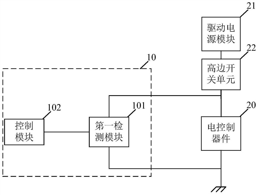
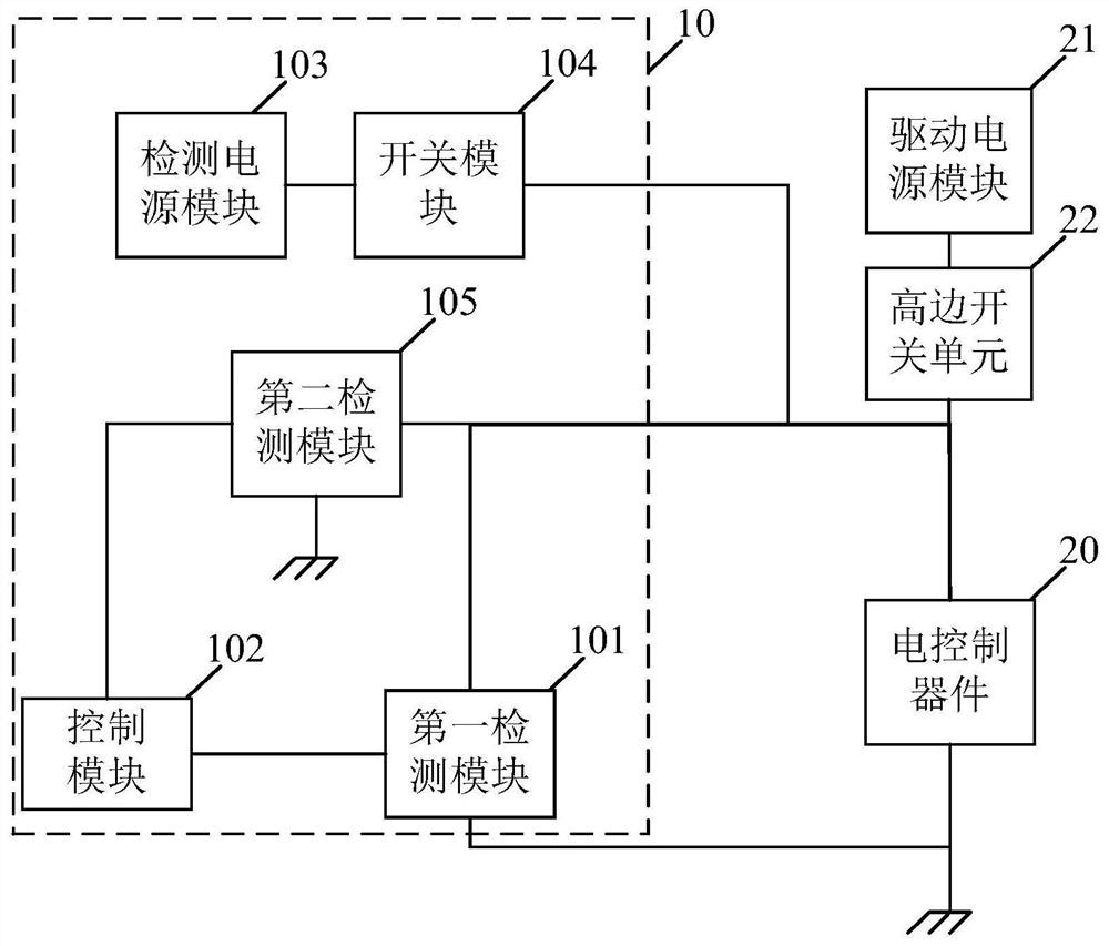
The embodiment of the invention relates to the technical field of electronics, and discloses a detection circuit and detection method of an electric control device. In some embodiments of the invention, the detection circuit comprises a driving loop used for detecting an electric control device;c the driving loop comprises a high-side switch unit; the detection circuit also comprises a first detection module and a control module; the first end of the first detection module is connected with the first end of the electric control device, the second end of the first detection module is connectedwith the second end of the electric control device, and the third end of the first detection module is connected with the control module; the control module is used for acquiring a first electric signal of the third end of the first detection module; and according to the first electric signal of the third end of the first detection module, whether the driving circuit of the electric control devicefails is judged. In this embodiment, it is possible to diagnose a fault in the driving loop of the electrical control device.

Description

technical field [0001] The embodiments of the present invention relate to the field of electronic technology, and in particular to a detection circuit and a detection method of an electrical control device. Background technique [0002] At present, the replacement of fuel vehicles by electric vehicles has become the development trend of the automobile industry. Due to the high power of the electric vehicle motor itself, the battery packs currently used are basically solutions with high voltage and low current or low voltage and high current. However, even if the voltage of the battery pack is low, it is far beyond the safe voltage. Therefore, the controller controls the high-voltage circuit by using relays to achieve indirect control. However, the relay is a mechanical switch after all. After a long time of work, there may be an aging problem, which will further lead to failure of the relay or the wiring harness connected to the relay. These conditions have a great impact ...

Claims


Application Information

Patent Timeline
IPC IPC(8): G01R31/28G05B23/02
CPCG01R31/282G05B23/0213G01R31/006G01R31/3277G01R31/52B60L3/0046
Inventor 傅焱辉杜宝海吴国秀
Owner CONTEMPORARY AMPEREX TECH CO
Learn More