
Medical rehabilitation equipment

A technology of equipment and connecting frame, which is applied in the field of medical rehabilitation, can solve the problem of single rehabilitation function, and achieve the effect of improving experience and applicability

Inactive Publication Date: 2021-03-09
德清创赢机械科技有限公司
View PDF9 Cites 0 Cited by
  • Summary
  • Abstract
  • Description
  • Claims
  • Application Information

AI Technical Summary

Problems solved by technology

[0005] Aiming at the deficiencies of the prior art, the present invention provides a medical rehabilitation equipment, which solves the problem that the rehabilitation function of the traditional rehabilitation equipment is relatively single

Method used


Image

  • Medical rehabilitation equipment
  • Medical rehabilitation equipment
  • Medical rehabilitation equipment

Examples


Embodiment 1

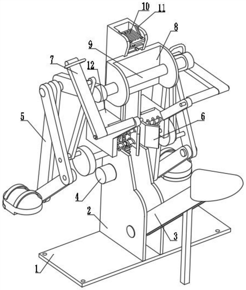
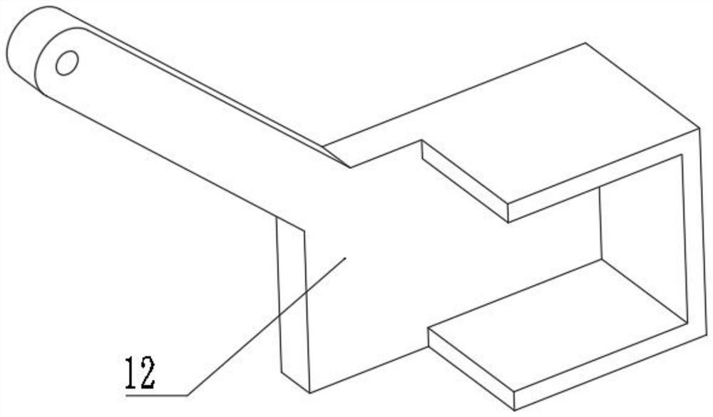
[0034] A medical rehabilitation device, such as Figure 1-Figure 4 As shown, it includes a fixed base plate 1, the upper surface of the fixed base plate 1 is welded with a connecting frame 2, the inside of the connecting frame 2 is provided with a seat mechanism 3, the left side of the connecting frame 2 is fixedly installed with a servo motor 4, and the two ends of the connecting frame 2 The sides are welded with a support sleeve 12, the inside of the support sleeve 12 is provided with a clamping mechanism 6, the front part of the connecting frame 2 is welded with a fixed plate 8, the inside of the fixed plate 8 is welded with a handrail bar 9, and the surface of the handrail bar 9 is provided with The lower limb movement mechanism 5 is provided with a bracket mechanism 10 on the inner wall of the connecting frame 2 .

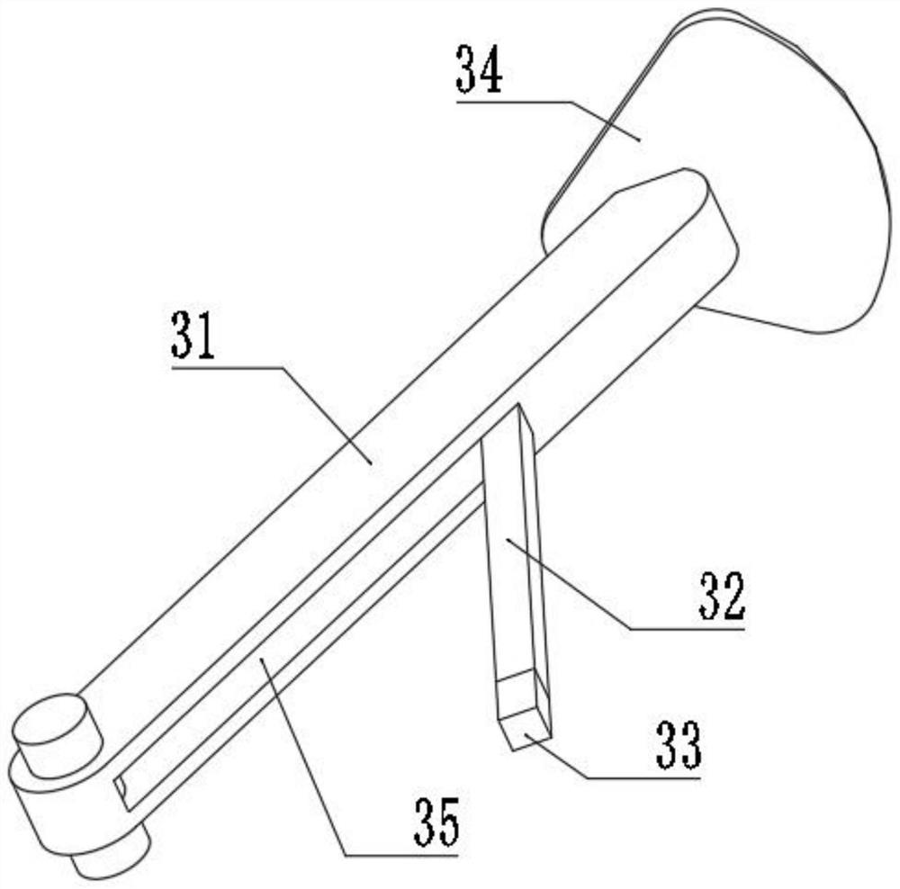
[0035] Further, the seat mechanism 3 includes a connecting strut 31, the upper surface of the connecting strut 31 is connected with a seat cushion 34 by bolts...

Embodiment 2

[0040] A medical rehabilitation device, such as Figure 7-Figure 8 As shown, the clamping mechanism 6 includes a splint 61, two telescopic rods 63 are welded on the left side of the splint 61, the left end of the telescopic rod 63 is welded on the right side of the support sleeve 12, the surface of the telescopic rod 63 is sleeved with a spring 62, Push the connecting rod 31 between the two clamping plates 61 by pushing, and it will be clamped and fixed by the action of the spring 62, so that the entire seat mechanism 3 is contracted and fixed.

[0041] Further, there are two clamping mechanisms 6, and the two clamping mechanisms 6 are symmetrically distributed with the centerline of the connecting frame 2 as a symmetrical axis. The structure of the splint 61 is V-shaped, and the V-shaped structure can be During the pushing process, the connecting rod 31 is directly pushed and slid in automatically, and tightened and fixed.

[0042] Furthermore, the support mechanism 10 inclu...


PUM


Abstract

The invention relates to the technical field of medical rehabilitation, and discloses medical rehabilitation equipment. The medical rehabilitation equipment comprises a fixed bottom plate, a connecting frame is welded to the upper surface of the fixed bottom plate, a seat mechanism is arranged inside the connecting frame, a servo motor is fixedly installed on the left side of the connecting frame,supporting sleeves are welded to the two sides of the connecting frame, a clamping mechanism is arranged in each supporting sleeve, a fixing plate is welded to the front portion of the connecting frame, a lower limb movement mechanism is arranged on the surface of a handrail rod, and a support mechanism is arranged on the inner wall of the connecting frame. According to the medical rehabilitationequipment, through a meshing effect of a driving gear and a transmission gear, a connecting shaft is driven to rotate to drive two pedals to imitate human leg movement, without large overall movementamplitude or secondary injury to a patient, thus passive rehabilitation training can be conducted on the legs of the human body, and the condition of force acting on a user in the rehabilitation process is reduced.

Description

technical field [0001] The invention relates to the technical field of medical rehabilitation, in particular to a medical rehabilitation equipment. Background technique [0002] Rehabilitation equipment is mainly to help patients carry out passive exercise and daily activities, and promote rehabilitation equipment; most of them are made of stainless steel, iron, plastic, wood, and are made into required parts through machining, welding, injection molding and other production processes. Or hundreds of parts are assembled into a rehabilitation device, and the design tends to be intelligent. The rehabilitation device can meet the daily passive activities of the upper and lower limbs of the patient, so that the human body muscles will not atrophy. [0003] At present, in the daily rehabilitation process of some leg rehabilitation patients, the rehabilitation function is relatively single, and the range of motion is too large, which may cause secondary damage to the legs during t...

Claims


Application Information

Patent Timeline
Patent Type & Authority Applications(China)
IPC IPC(8): A61H1/02
CPCA61H1/0237A61H1/0274A61H2201/1207A61H2205/10A61H2205/06
Inventor 姚晓辉姚冬闻琦
Owner 德清创赢机械科技有限公司
Learn More