
Shearing head of reinforcing steel bar batch shearing equipment for construction

A technology for shearing equipment and construction. It is applied in metal processing equipment, maintenance and safety accessories, manufacturing tools, etc. It can solve the problems of poor durability of shearing equipment, continuous operation of the mounting seat without cooling, and short service life.

Inactive Publication Date: 2021-03-09
黄婕妤
View PDF0 Cites 0 Cited by
  • Summary
  • Abstract
  • Description
  • Claims
  • Application Information

AI Technical Summary

Problems solved by technology

[0002] Steel bars are very commonly used building materials. When used on construction sites, it is often necessary to cut long steel bars into small sections. In order to improve construction efficiency and ensure uniform cutting lengths, many construction parties now choose mechanical shearing, but the existing shearing equipment The shearing knife is built-in. During continuous shearing, the metal is continuously extruded to generate high temperature. The cutter head and the mounting seat of the cutter head will not be cooled during continuous work, and the service life is short, which makes the durability of the shearing equipment poor and cannot adapt to large-scale shearing. cut tasks

Method used


Image

  • Shearing head of reinforcing steel bar batch shearing equipment for construction
  • Shearing head of reinforcing steel bar batch shearing equipment for construction
  • Shearing head of reinforcing steel bar batch shearing equipment for construction

Examples


Embodiment Construction

[0023] The following will clearly and completely describe the technical solutions in the embodiments of the present invention with reference to the accompanying drawings in the embodiments of the present invention. Obviously, the described embodiments are only some, not all, embodiments of the present invention. Based on the embodiments of the present invention, all other embodiments obtained by persons of ordinary skill in the art without making creative efforts belong to the protection scope of the present invention.

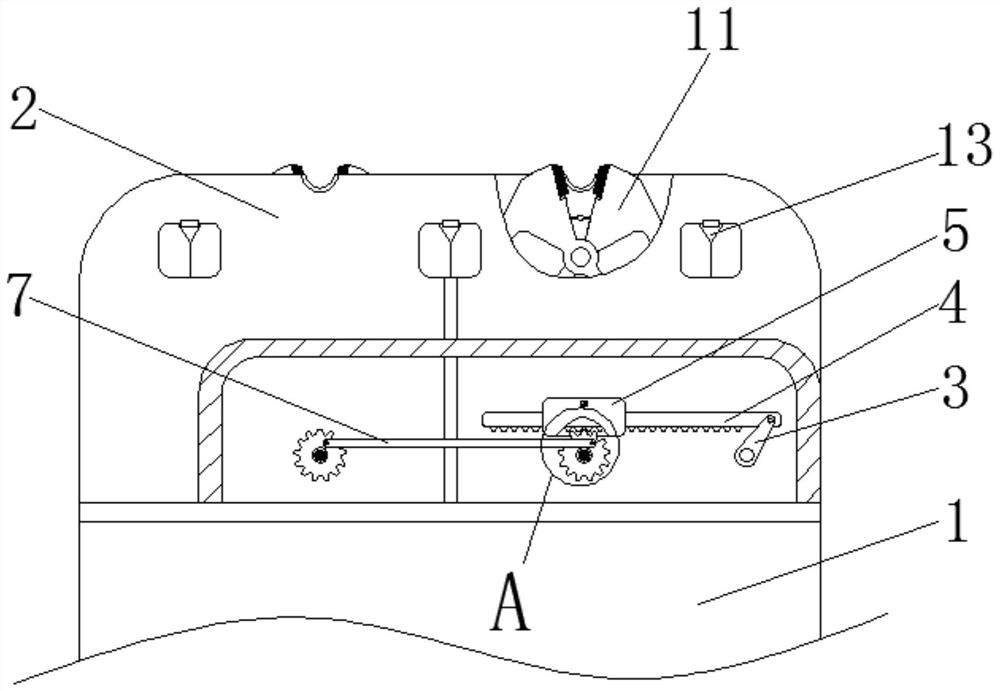
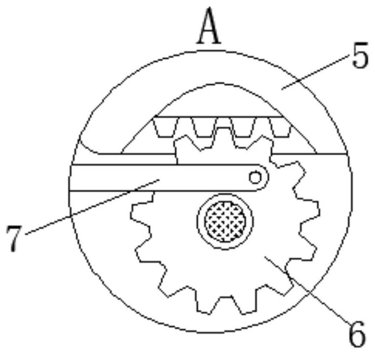
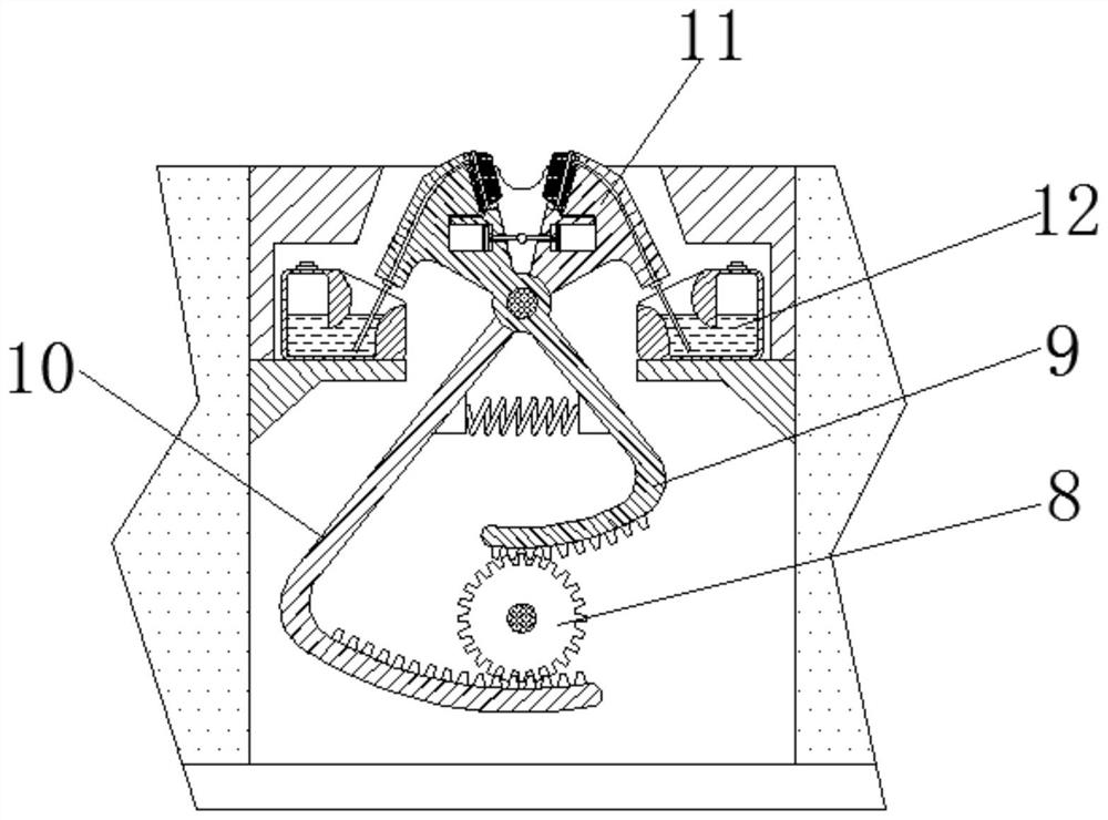
[0024] see Figure 1-4 , a cutting head of batch shearing equipment for steel bars for construction, comprising a connecting seat 1, the upper end of the connecting seat 1 is fixedly connected with a mounting head 2, the front side of the mounting head 2 is provided with a driving crank 3, and the end of the driving crank 3 A rack 4 is movably connected, and the outside of the rack 4 is sleeved with a limit sleeve 5. A toggle gear 6 is arranged below the limit...


PUM


Abstract

The invention relates to the technical field of reinforcing steel bar shearing equipment, and discloses a shearing head of reinforcing steel bar batch shearing equipment for construction. The shearinghead comprises a connecting seat, a mounting head is fixedly connected to the upper end of the connecting seat, a driving crank is arranged on the front side of the mounting head, a rack is movably connected to the tail end of the driving crank, a limiting sleeve sleeves the rack, and a shifting gear is arranged below the limiting sleeve and movably connected with a synchronous connecting rod. According to the shearing head of the reinforcing steel bar batch shearing equipment for construction, when shearing pliers are separated from the shearing position, a push rod connected between coolingpistons pulls the cooling pistons to generate negative pressure in a cavity, and a water drawing pipe absorbs water from a water tank and fills a coil pipe in a cooling groove to absorb heat generated by shearing reinforcing steel bars; and when a shearing wheel drives the shearing pliers to approach for shearing again, the push rod pushes the cooling pistons to extrude high-temperature cooling water, so that a high-temperature tool bit of the shearing plier is cooled through shearing action, and the service life of the tool bit and a fixing device thereof is prolonged.

Description

technical field [0001] The invention relates to the technical field of steel bar shearing equipment, in particular to a shearing head of a steel bar batch shearing equipment for construction. Background technique [0002] Steel bars are very commonly used building materials. When used on construction sites, it is often necessary to cut long steel bars into small sections. In order to improve construction efficiency and ensure uniform cutting lengths, many construction parties now choose mechanical shearing, but the existing shearing equipment The shearing knife is built-in. During continuous shearing, the metal is continuously extruded to generate high temperature. The cutter head and the mounting seat of the cutter head will not be cooled during continuous work, and the service life is short, which makes the durability of the shearing equipment poor and cannot adapt to large-scale shearing. cut tasks. Contents of the invention [0003] (1) Solved technical problems [0...

Claims


Application Information

Patent Timeline
IPC IPC(8): B21F11/00B23Q11/10
CPCB21F11/00B23Q11/1092
Inventor 黄婕妤
Owner 黄婕妤
Learn More