Rotary mold injection molding and cooling forming equipment for plastic particles
A technology of cooling forming and plastic particles, applied in metal processing and other directions, can solve the problems of uneven end face of cutter, plastic particles with wool, wire drawing, etc., to avoid wire drawing and ensure smoothness.
- Summary
- Abstract
- Description
- Claims
- Application Information
AI Technical Summary
Problems solved by technology
Method used
Image

Examples
Embodiment 1
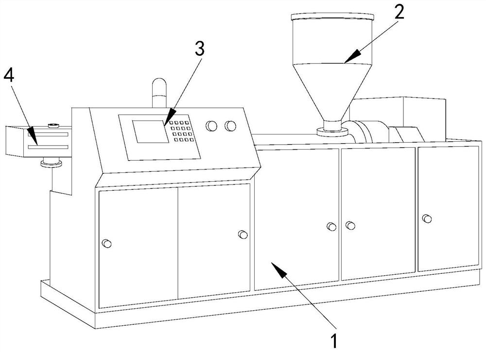
[0026] Example 1: Please refer to Figure 1-Figure 5 , the specific embodiments of the present invention are as follows:
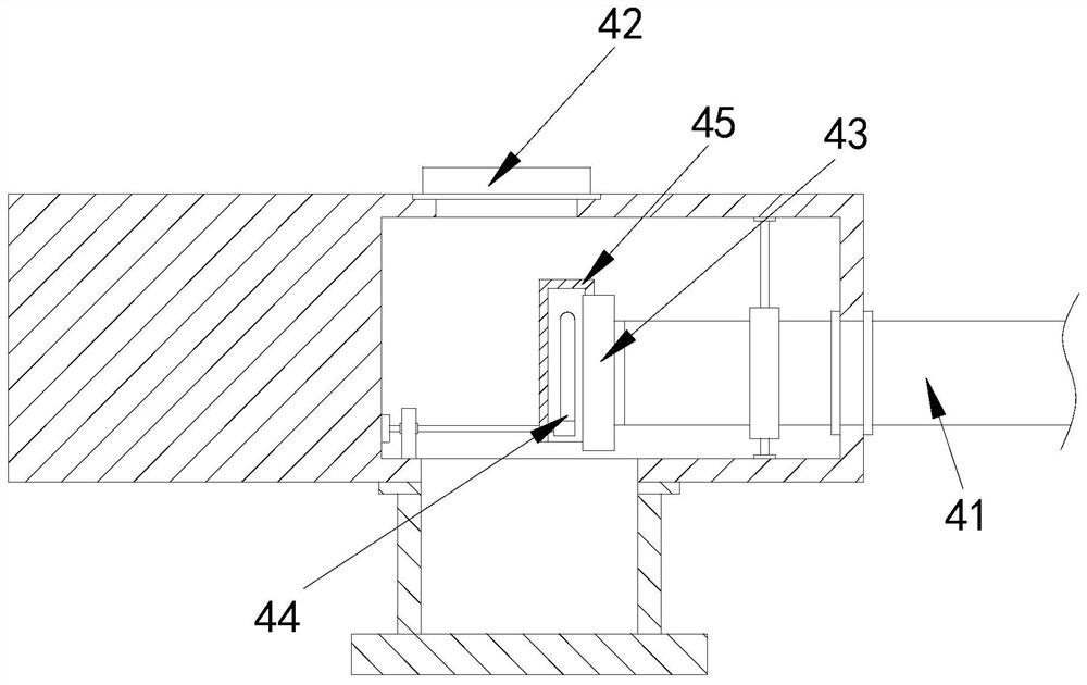
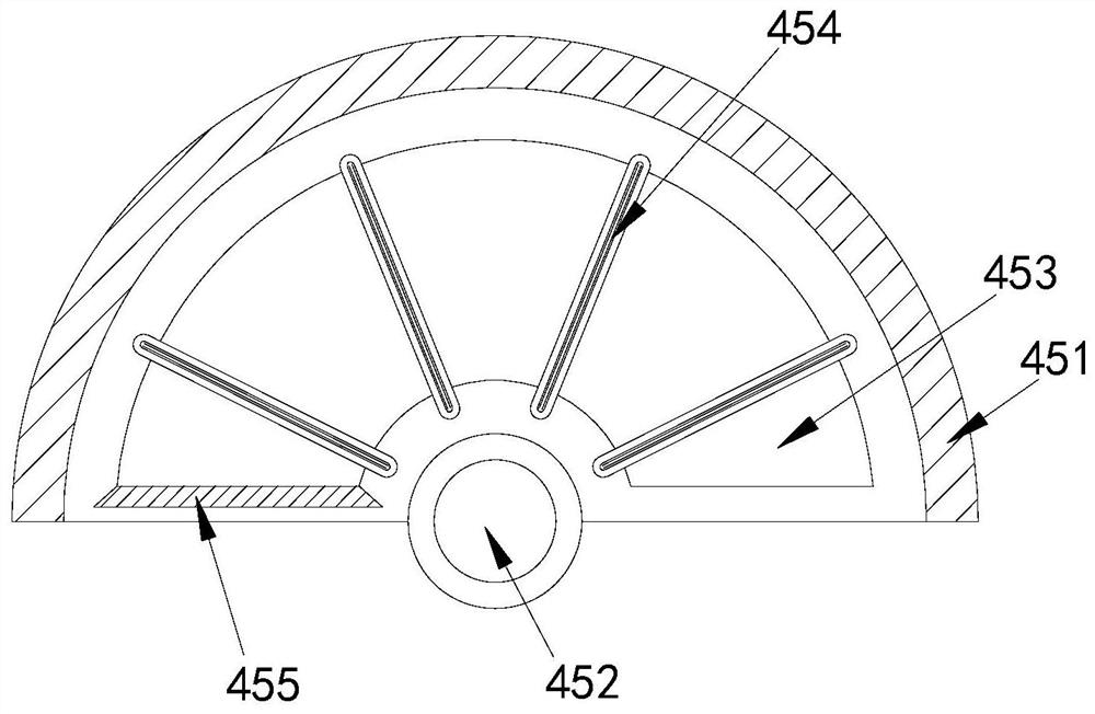
[0027] Its structure includes a machine base 1, a feed box 2, a control panel 3, and a discharge device 4. The top of the machine base 1 is provided with a feed box 2, the control panel 3 is located at the front end of the machine base 1, and the outlet The material discharge device 4 is arranged on the side end of the machine base 1, and the discharge device 4 includes a discharge pipe 41, a heat dissipation port 42, a discharge port 43, a cutter 44, and a material guide cover 45, and the discharge pipe 41 runs through the Inside the discharge device 4, the heat dissipation port 42 is positioned at the top of the discharge device 4, the discharge port 43 is connected to the end of the discharge pipe 41, and the cutter 44 is installed at the front end of the discharge port 43, The material guide cover 45 is located outside the cutter 44 .
[0028] The ma...
Embodiment 2
[0032] Example 2: Please refer to Figure 6-Figure 8 , the specific embodiments of the present invention are as follows:
[0033]The contact block a4 includes an installation groove b1, a water flow hole b2, a water spray head b3, and a water storage device b4. There are six installation grooves b1 arranged laterally on the upper end surface of the contact block a4. The water flow holes b2 Connected to the bottom of the installation groove b1, the water spray head b3 is installed at the bottom of the water flow hole b2, the water storage device b4 is set in the middle of the water flow hole b2, and the end surface of the water spray head b3 is a circular arc shape, which is conducive to spraying water mist in a larger range on the plasticizer on the cutter 44 end faces.
[0034] The water storage device b4 includes a water storage tank b41, a sponge b42, a vent pipe b43, a rubber ring b44, and a lower pressure cover b45. The inside of the water storage tank b41 is provided wi...
PUM
 Abstract
Description
Claims
Application Information
 - R&D
- Intellectual Property
- Life Sciences
- Materials
- Tech Scout
- Unparalleled Data Quality
- Higher Quality Content
- 60% Fewer Hallucinations
Browse by: Latest US Patents, China's latest patents, Technical Efficacy Thesaurus, Application Domain, Technology Topic, Popular Technical Reports.
© 2025 PatSnap. All rights reserved.Legal|Privacy policy|Modern Slavery Act Transparency Statement|Sitemap|About US| Contact US: help@patsnap.com