Plate rolling fork hoisting logistics tray
A coiling fork and logistics technology, applied in packaging, unloading devices, transportation and packaging, etc., can solve the problems of steel coil bumping, no reinforcement materials and methods, and low efficiency
- Summary
- Abstract
- Description
- Claims
- Application Information
AI Technical Summary
Problems solved by technology
Method used
Image

Examples
Embodiment Construction
[0046] The technical solutions in the embodiments of the present invention will be clearly and completely described below in conjunction with the embodiments of the present invention. Apparently, the described embodiments are only some of the embodiments of the present invention, not all of them. Based on the embodiments of the present invention, all other embodiments obtained by persons of ordinary skill in the art without making creative efforts all involve the protection scope of the present invention.
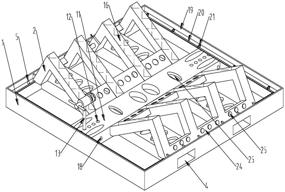
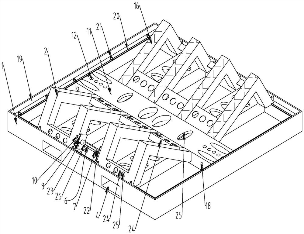
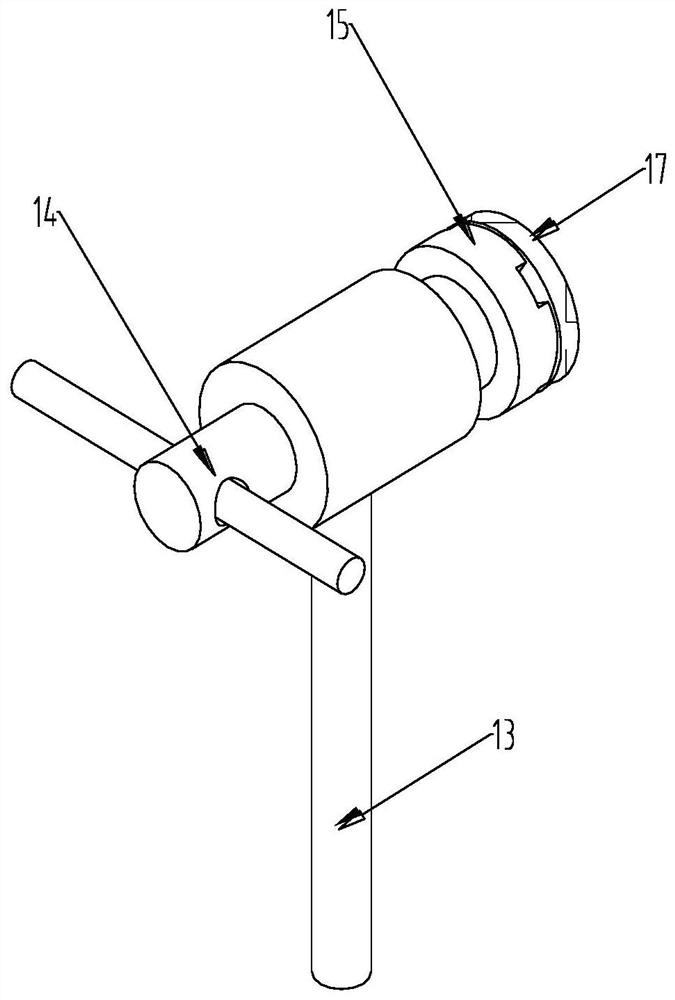
[0047] Such as Figure 1 to Figure 9 As shown, this example proposes
[0048] A logistics pallet hoisted by a coiling fork, including a base 1, a support frame is arranged on the base 1, the support frame includes two oppositely arranged support plates 2, the support plates 2 are used to receive the coil plate 3, and there are several support frames, The base 1 also includes several forklift slots 4 and hoisting holes 5,
[0049] The strap locking device 6 is arranged bet...
PUM
 Abstract
Description
Claims
Application Information
PatSnap Eureka turns technology decisions into work you can execute. Powered by our Innovation Knowledge Graph, it runs expert workflows across engineering, life sciences, materials and intellectual property. Get your review-ready output in minutes.


