
Pallet box stacking structure

A pallet box, stacking technology, applied in rigid containers, containers, packaging and other directions, can solve the problems of difficult stacking guidance, damage to the box cover, high cost, and achieve the effects of convenient forklift operation, reliable position limit and simple structure

Active Publication Date: 2015-10-28
CHINA INTERNATIONAL MARINE CONTAINERS (GROUP) CO LTD +2
View PDF10 Cites 0 Cited by
  • Summary
  • Abstract
  • Description
  • Claims
  • Application Information

AI Technical Summary

Problems solved by technology

Due to the thin end wall of this kind of stacking structure, the size of the stacking limiter is small (should not exceed the thickness of the end wall), and the size of the outer circular surface of the round steel for guiding is small. During the stacking operation of the forklift, the lower layer The limit parts of the pallet box are not easy to guide into the stacking space of the chassis of the upper pallet box. The slope at one end of the round steel needs to be machined, which is costly and the guide size is small, so it is not easy to stack and guide. , poor reliability of horizontal limit
If the pallet box has a box cover, the upper pallet box will be stacked on the box cover of the lower pallet box, which is easy to cause damage to the box cover, especially for the box cover with a convex shape, it may not be stackable
[0008] As the pallet box tends to be light-weight design, and the end and side walls are relatively thin, the existing stacking structure cannot fully meet the above requirements

Method used


Image

  • Pallet box stacking structure
  • Pallet box stacking structure
  • Pallet box stacking structure

Examples


Embodiment Construction

[0048] The present invention will be further described below in conjunction with accompanying drawing.

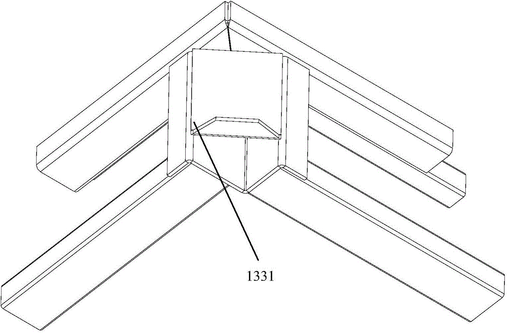
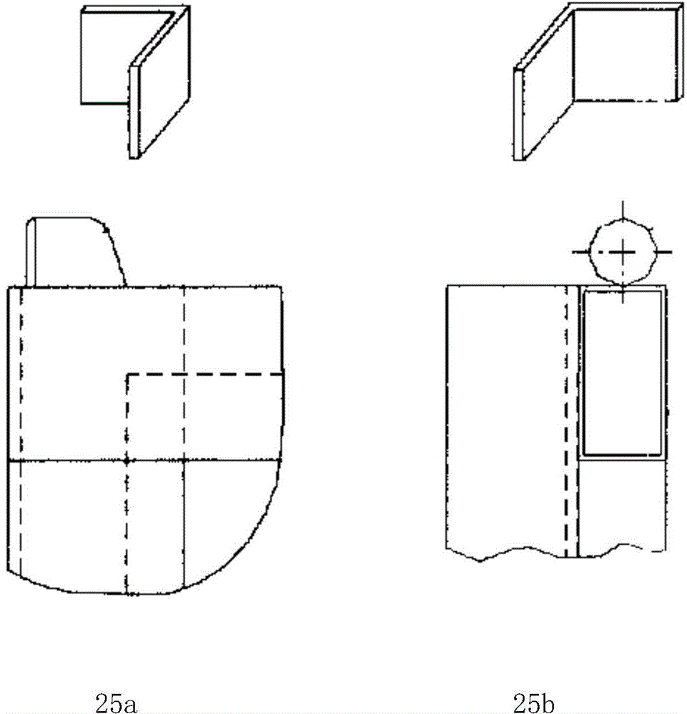
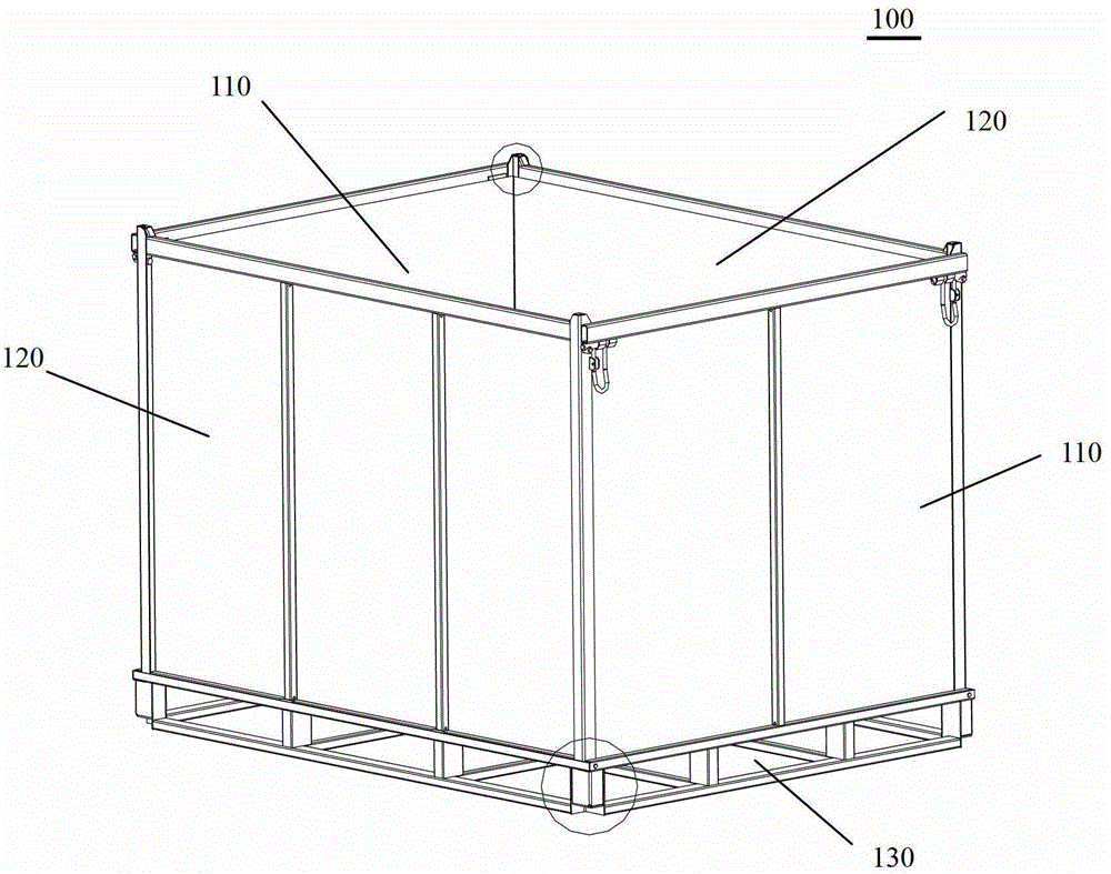
[0049] Such as Figure 1-15As shown, the pallet box is composed of a chassis 130, two end walls 110 and two side walls 120. A stacking space 134 is arranged at the four corners of the bottom of the chassis 130. The stacking space 134 is adapted to the pallet box limiter below. When two pallet boxes are stacked together, there are no side-by-side parts, which saves space and avoids interference. Stacking space 134 is formed by chassis corner post 132, and the cross-section of chassis corner post 132 is L-shaped, and the two supporting arms of L shape are corner post uprights 1321, 1322, and the space between corner post uprights forms cuboid stacking space 134 . In order to increase the rigidity of the chassis corner post 132, two bent side plates 1323 can be added to improve the rigidity of the chassis corner post, as Figure 23 shown.

[0050] The limiting device of th...


PUM


Abstract

The invention discloses a stacking structure for a tray box. Base plate corner columns with L-shaped cross sections are arranged at four corners of the bottom of a base plate respectively to form stacking space, end wall stand columns and side wall stand columns extend out of an upper cross beam to be used as limiting devices to be adaptive to the stacking space, inclined angles are arranged at upper ends of the end wall stand columns, guiding pieces with inclined surfaces are arranged at upper ends of the side wall stand columns, the inclined angels and the inclined surfaces are matched with two surfaces of the base plate corner columns at the position of the base plate stacking space respectively so that stacking horizontal guiding along the end wall direction and the side wall direction is achieved. The portions of the end wall stand columns and side wall stand columns, which extend out of the upper cross beam, can be adjusted in height, different bearing modes can be achieved, and stacking bearing modes can be achieved for tray boxes with covers. The stacking structure is particularly suitable for stacking of the detachable or foldable tray boxes with thin end and side walls.

Description

technical field [0001] The invention relates to the technical field of pallet boxes. Background technique [0002] In order to reduce the transportation cost and storage space of pallet boxes, pallet boxes are generally designed to be stackable after loading. The stacking structure generally needs to have the following functions: [0003] 1. Limit the horizontal movement of stacked pallet boxes to prevent the upper pallet boxes from sliding down. Especially during transportation, the upper pallet boxes are more likely to slide down. Therefore, the limit must be reliable and the limit parts must be large enough . [0004] 2. To withstand a large enough stacking weight in the vertical direction. The size of the stacking load-carrying capacity determines the loading weight and stackable height of the pallet box, which reflects the performance of the pallet box. [0005] 3. The stacking operation is convenient. The stacking structure of the pallet box should have a guide part...

Claims


Application Information

Patent Timeline
Patent Type & Authority Patents(China)
IPC IPC(8): B65D21/032B65D19/06B65D19/38
Inventor 苏继军鲁亮倪建生
Owner CHINA INTERNATIONAL MARINE CONTAINERS (GROUP) CO LTD
Features
  • Generate Ideas
  • Intellectual Property
  • Life Sciences
  • Materials
  • Tech Scout
  • Unparalleled Data Quality
  • Higher Quality Content
  • 60% Fewer Hallucinations
Learn More