
Simple auxiliary door for pets

An auxiliary door and simple technology, applied in the field of auxiliary doors, can solve the problems of easy leakage of air-conditioning and cold air, inconvenience for the owner, etc., and achieve the effect of improving convenience and practicability, and facilitating going out.

Inactive Publication Date: 2021-03-09
杭州优安客网络科技有限公司
View PDF2 Cites 0 Cited by
  • Summary
  • Abstract
  • Description
  • Claims
  • Application Information

AI Technical Summary

Problems solved by technology

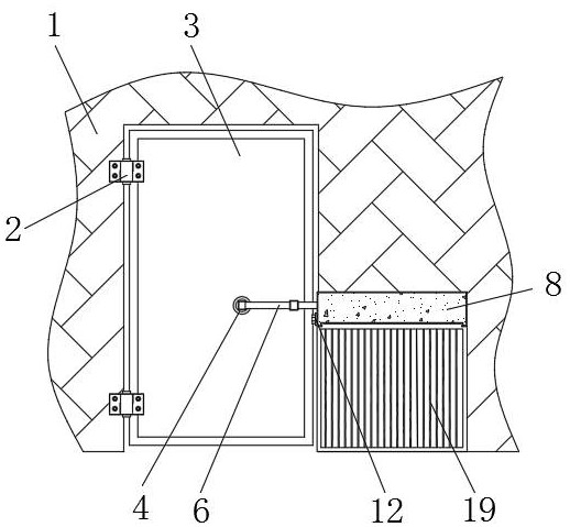
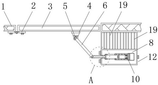
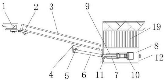
[0004] The purpose of the present invention is to provide a simple auxiliary door for pets to solve the problem of turning on the air conditioner in summer and when the pet goes out, the owner needs to help open the door or leave a gap for the door. If the owner opens the door, it will cause inconvenience to the owner. , if the door is left open, air-conditioning air-conditioning is easy to leak out

Method used


Image

  • Simple auxiliary door for pets
  • Simple auxiliary door for pets
  • Simple auxiliary door for pets

Examples


Embodiment 1

[0026] Embodiment 1: A simple auxiliary door for pets, comprising a board wall 1, a hinge 2, a room door 3, an electric push rod 10 and an infrared sensor 22, the inside of the board wall 1 is movably connected with a room door 3 through the hinge 2, One side of the room door 3 is adsorbed with a suction cup 4, and the side of the suction cup 4 away from the room door 3 is fixed with a connecting seat 5. The inside of the connecting seat 5 is movably connected with a hinged rod 6 through a rotating shaft, and the inside of the connecting seat 5 is provided with a hinged rod. 6 positioning slots that cooperate with each other, through this design, the hinge rod 6 is limited, and the jamming caused by the excessive rotation angle of the hinge rod 6 is avoided, thereby facilitating the rotation of the hinge rod 6 and improving the convenience of the device.

[0027] One side of the hinge rod 6 away from the room door 3 is movably connected with a pull rod 7 through the hinge shaft...

Embodiment 2

[0030] Embodiment 2: A simple auxiliary door for pets, including a room door 3, an infrared sensor 22, an electric push rod 10, a connecting rod, a rack, a gear, a storage turntable, a drawstring, and a suction cup 4. When a pet enters the passage, The pet cuts off the transmission signal of the infrared sensor 22, the infrared sensor 22 transmits the signal to the controller, the controller controls the electric push rod 10 to move, the electric push rod 10 drives the connecting rod to move synchronously, the top of the connecting rod is connected to a rack, and the rack moves Drive the gear meshed with the rack to rotate, the gear and the storage turntable are fixed, and the rotation of the gear drives the storage turntable to rotate synchronously. At this time, the rotation of the storage turntable makes the drawstring wrapped around the outer wall of the turntable wind up, and the drawstring is stored. The end of the drawcord away from the turntable is connected to the sucti...


PUM


Abstract

The invention discloses a simple auxiliary door for pets. The auxiliary door comprises a siding wall, hinges, a room door, an electric push rod and an infrared sensor, wherein the interior of the siding wall is movably connected with the room door through the hinges, a sucker is adsorbed to one side of the room door, a connecting base is fixed to one side, away from the room door, of the sucker, ahinge rod is movably connected to the interior of the connecting base through a rotating shaft, a pull rod is movably connected to the side, away from the room door, of the hinge rod through a hingeshaft, a fixing base is arranged on the side, away from the room door, of the pull rod, a first open groove matched with the pull rod is formed in the fixing base, the electric push rod is fixed to the side, away from the room door, in the first open groove, and the side, close to the room door, of the electric push rod is fixed to the pull rod. An owner does not need to help to open the door fora pet requiring to go out to go to the toilet, the room door does not need to be opened by a certain gap for a long time, the pet can go out conveniently, and convenience is brought to the owner.

Description

technical field [0001] The invention relates to the technical field of auxiliary doors, in particular to a simple auxiliary door for pets. Background technique [0002] With the continuous development of society, in order to facilitate the use of users, various auxiliary doors are also obtained continuously. The existing auxiliary doors possess various functions and realize diversification. The smart door that can automatically open and close the auxiliary door solves the problem that the existing smart door cannot receive objects. The device has a smart door that can automatically open and close the auxiliary door. The mullite insulation brick tunnel furnace disclosed by the publication number CN110631359A, the invention is equipped with No. 1 electric push rod, furnace body entrance, No. 2 electric push rod, furnace body exit, infrared sensor, and the infrared sensor detects the mullite brick , convert the wavelength of the detected mullite brick into an electrical signal...

Claims


Application Information

Patent Timeline
Patent Type & Authority Applications(China)
IPC IPC(8): E06B7/32E06B7/00
CPCE06B7/00E06B7/32
Inventor 严雪纯
Owner 杭州优安客网络科技有限公司
Learn More